Wavelength division multiplexing optical transmission system

Inactive Publication Date: 2006-01-26
FUJITSU LTD
View PDF7 Cites 68 Cited by
  • Summary
  • Abstract
  • Description
  • Claims
  • Application Information

AI Technical Summary

Benefits of technology

[0016] The present invention has been accomplished in view of the above problems, and it is a first object of the present invention to enable stable control in respective stations even at the time of increasing or decreasing the number of wavelengths, in a WDM light transmission system, when the control of the optical signal power of the respective wavelengths included in the WDM light is executed in a plurality of stations on the optical transmission line. It is a second object of the present invention to ensure excellent tra

Problems solved by technology

When with respect to the conventional WDM optical transmission system including such a path changing station, the power of optical signals of the respective wavelengths is controlled by a method similar to the point-to-point configuration, there are problems described below.
Therefore it becomes very difficult to adjust the optical signal power of the increased wavelength to an appropriate level by the optical add-drop station 107.
As a result, increase in the number of wavelengths may not be completed normally, or retry of control has to be repeated, thereby taking a long time for activation (first problem).
Particularly, when the optical add-drop stations (or the optical cross-connect stations) are connected in multiple stages, the influence of such a state becomes noticeable, thereby causing a problem.
Moreover, in addition to the first problem, the optical amplifiers provided in the wavelength multiplexing station and the repeating and amplifying station amplify and output signal components in the WDM light, and at the same time, output the spontaneously emitted light (ASE) as noise components.
In this case, unnecessary light of only the ASE without including the signal component, is output from the optical add-drop station 107 for the wavelength λ1 (see point C in FIG. 16), and is further transmitted to the downstream side, thereby causing deteriora

Method used


Image

  • Wavelength division multiplexing optical transmission system
  • Wavelength division multiplexing optical transmission system
  • Wavelength division multiplexing optical transmission system

Examples


first embodiment

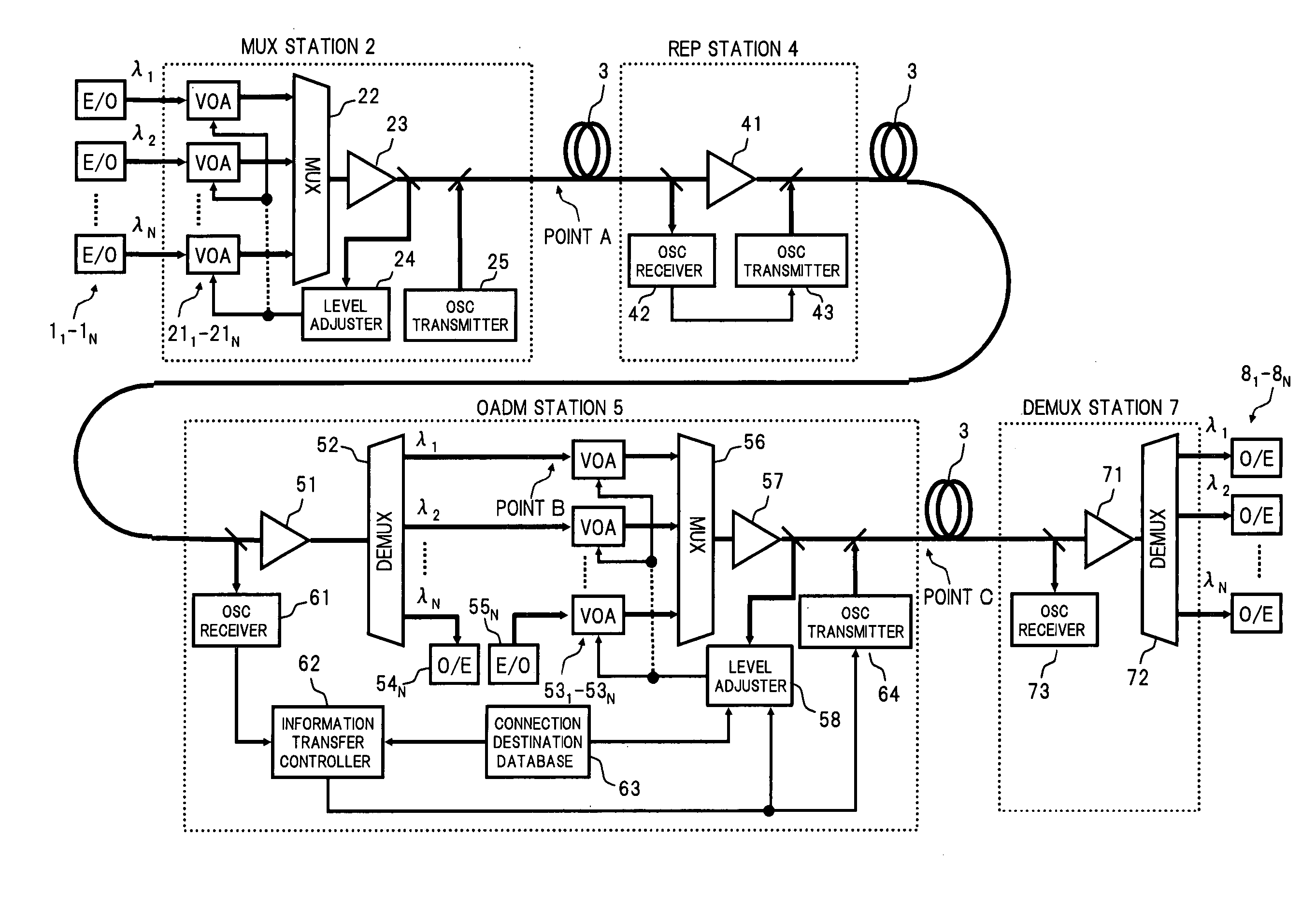
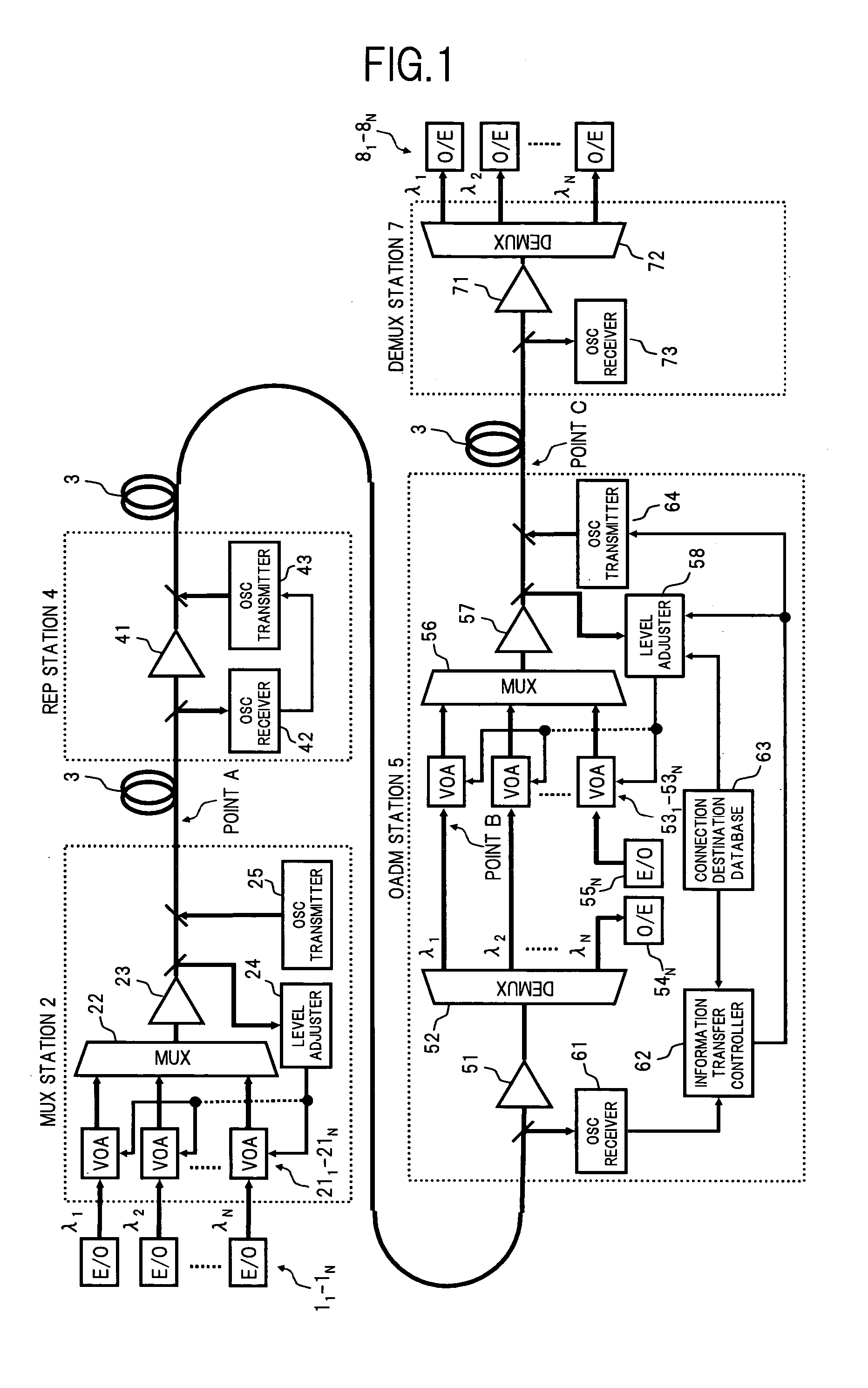
[0041]FIG. 1 is a diagram showing a configuration of a WDM optical transmission system according to the present invention.

[0042] In FIG. 1, a WDM optical transmission system in the present embodiment comprises, for example: a plurality of (here, N) optical transmitters (E / O) 11 to 1N; a wavelength multiplexing (MUX) station 2 which multiplexes optical signals output from the respective optical transmitters 11 to 1N to generate WDM light and transmits the WDM light to an optical transmission line 3 together with an optical supervisory channel (OSC); a repeating and amplifying station (REP) 4 arranged on the optical transmission line 3 for amplifying and outputting the input WDM light; an optical add-drop station (OADM) 5 arranged on the optical transmission line 3 for changing over the path of optical signals of respective wavelengths; a wavelength demultiplexing (DEMUX) station 7 which generates optical signals of respective wavelengths by demultiplexing the WDM light propagating on...

second embodiment

[0086] Next the present invention will be described below.

[0087] In the first embodiment, the description was for a case in which the control of the optical signal power for the respective wavelengths λ1 to λN included in the WDM light is performed by using the variable optical attenuator provided for each wavelength. However, other than the above described method of controlling the optical signal power for the respective wavelengths λ1 to λN, there are known other methods of controlling a tilt of power with respect to the wavelengths of all optical signals included in the WDM light, for example, by using a gain tilt characteristic of a rare earth doped optical fiber amplifier, or by adjusting a plurality of wavelengths of pumping light or power ratio in a Raman amplifier. Therefore in the second embodiment, a WDM optical transmission system in which the level control for each wavelength by using the variable optical attenuator in the first embodiment, and the above described tilt c...

third embodiment

[0096] Next the present invention will be described below.

[0097] In the third embodiment, as an application example of the aforementioned first embodiment, a WDM optical transmission system also corresponding to a pre-emphasis control function will be described. Pre-emphasis control refers to control for rendering the power of optical signals of the respective wavelengths nonuniform in the wavelength multiplexing station on the transmission side, in order to equalize the optical signal to noise ratio (OSNR) in each wavelength after the WDM transmission.

[0098]FIG. 9 is a diagram showing the configuration of a main part of the WDM optical transmission system according to the third embodiment of the present invention.

[0099] The overall configuration of the WDM optical transmission system in this embodiment is a system configuration for performing two-way WDM optical transmission in which two configurations of the first embodiment are combined so as to correspond to up link and down l...


PUM


Abstract

A WDM optical transmission system of the invention has a configuration where WDM light generated at a wavelength multiplexing station is transmitted via a plurality of stations such as optical add-drop stations, arranged on an optical transmission line, and control of the power of the optical signals of respective wavelengths included in the WDM light is performed in the wavelength multiplexing station and the optical add-drop stations. A device is provided which communicates between stations, optical signals including information related to the control state of the optical signal power in each station, so that after control of the optical signal power at an upstream station is complete, control of the optical signal power at the downstream station is executed. As a result, stable control in respective stations can be performed even at the time of increasing or decreasing the number of wavelengths.

Description

BACKGROUND OF THE INVENTION [0001] (1) Field of the Invention [0002] The present invention relates to a wavelength division multiplexing (WDM) optical transmission system having a function for controlling the optical signal power of each wavelength included in WDM light, and more specifically, relates to a technique for stabilizing control of the optical signal power for a WDM optical transmission system in which an optical add-drop station and an optical cross-connect station are arranged on an optical transmission line. [0003] (2) Related Art [0004] In the basic configuration of a conventional WDM optical transmission system, as shown for example in FIG. 12, a point-to-point configuration is generally used, in which optical signals of wavelengths λ1 toλ3 from transmitters (E / O) 101 are multiplexed by a wavelength multiplexing (MUX) station 102 to transmit the WDM light to an optical transmission line 103, and the WDM light is repeatedly transmitted, while being amplified by a repe...

Claims


Application Information

Patent Timeline
IPC IPC(8): H04J14/02H04B10/07H04B10/077H04B10/079H04B10/27H04B10/29H04B10/296H04B10/297H04B10/524H04B10/564H04J14/00
CPCH04J14/0221
Inventor MORI, SHOTA
Owner FUJITSU LTD
Why Eureka
Try Eureka