Heat sink and heat spreader bonding structure

Inactive Publication Date: 2006-02-02
IND TECH RES INST
View PDF11 Cites 22 Cited by
  • Summary
  • Abstract
  • Description
  • Claims
  • Application Information

AI Technical Summary

Benefits of technology

[0009] The present invention has been accomplished under the circumstances in view. It is therefore the main object of

Problems solved by technology

A raise in temperature may cause the electronic device, for example, CPU, to shorten its service life.
A poor bonded between the copper heat spreader and the aluminum heat sink may cause the heat energy generated by the electronic device to be accumulated in the bottom side of the heat sink.
In this case, the electronic device may burn out due to overheat.
Further, if there is a crevice in the bonding interface between the copper heat spreader and the aluminum heat sink, a great heat resistance will be produced, thereby lowering the heat dissipation efficiency.
However, because the heat transfer efficiency of thermal grease or thermally conductive tap is much lower than copper and aluminum, the bonding interface will affect the heat transfer efficiency of the aluminum heat sink and the copper heat

Method used


Image

  • Heat sink and heat spreader bonding structure
  • Heat sink and heat spreader bonding structure
  • Heat sink and heat spreader bonding structure

Examples


Embodiment Construction

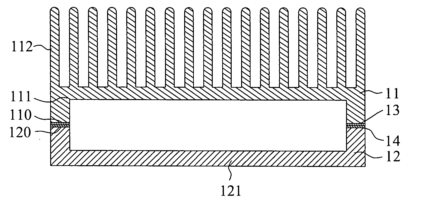
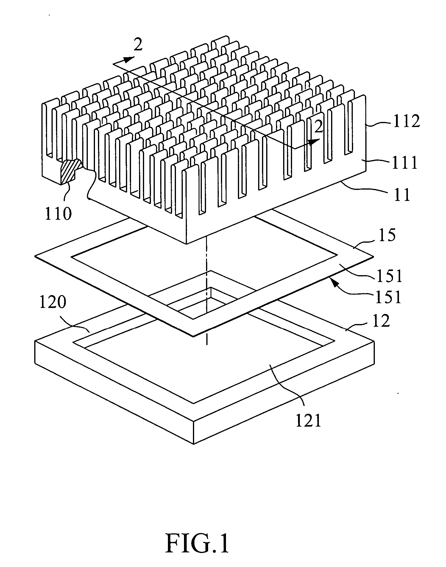
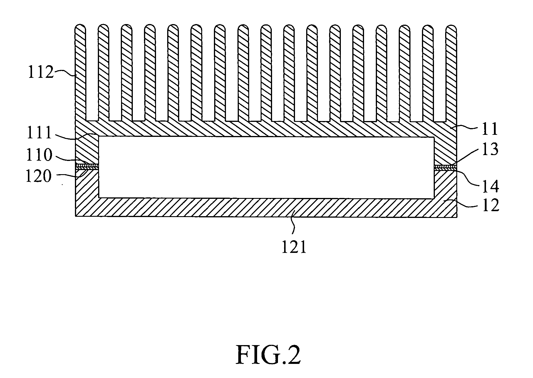
[0057] Referring to FIG. 1 and FIG. 2, a heat sink and heat spreader bonding structure in accordance with the first embodiment of the present invention is shown comprising a heat sink 11 and a heat spreader 12. The heat sink 11 is made of the copper of a first metal material, which has a first melting point t1. The head spreader 12 is also made of the copper of the first metal material.

[0058] This first embodiment also comprises a first bonding layer 13 and a second bonding layer 14. An intermediate element 15 is sandwiched in between the heat sink 11 and the heat spreader 12 and heated to a specific temperature t3, forming the first bonding layer 13 and the second bonding layer 14.

[0059] The aforesaid intermediate element 15 has an outside area 151 disposed in contact with the heat sink 11 and the heat spreader 12 respectively. The outside area 151 comprises a second metal material, which has a second melting point t2. According to this embodiment, the intermediate element 15 is ...


PUM

PropertyMeasurementUnit
Temperatureaaaaaaaaaa
Efficiencyaaaaaaaaaa
Melting pointaaaaaaaaaa

Abstract

A heat sink and heat spreader bonding structure includes a metal heat sink, a metal heat spreader, and an eutectic structure formed between the heat sink and the heat spreader by heating the heat sink and the heat spreader to a specific temperature of the eutectic temperature of the heat sink and the heat spreader but below the respective melting point of the heat sink and the heat spreader to cause the internal metal atoms of the heat sink and heat spreader to be rearranged. This bonding structure maintains the heat transfer efficiency of the bonding layer between the heat sink and the heat spreader, eliminates formation of crevice, heat resistance, and oxidation in the bonding layer.

Description

BACKGROUND OF THE INVENTION [0001] 1. Field of the Invention [0002] The present invention relates to a heat sink and heat spreader bonding structure and more particularly, to the bonding between different metal materials, for example, aluminum heat sink and copper heat spreader. [0003] 2. Description of Related Art [0004] Following market tendency of electronic products toward high power, high function and high speed, the corresponding thermal generating is relatively increased. A raise in temperature may cause the electronic device, for example, CPU, to shorten its service life. [0005] A heat dissipating device for electronic device is known comprising a copper heat spreader, and an aluminum heat sink bond to the copper heat spreader. The bonding layer between the copper heat spreader and the aluminum heat sink is decisive to heat dissipation efficiency. A poor bonded between the copper heat spreader and the aluminum heat sink may cause the heat energy generated by the electronic d...

Claims


Application Information

Patent Timeline
IPC IPC(8): H05K7/20B23K1/00G06F1/20H01L21/48H01L23/367
CPCH01L21/4882H01L23/367H01L2924/0002H01L2924/00
Inventor CHANG, SHIH-YINGCHUANG, TUNG-HANYEH, LAN-KAILIN, CHE-WEITSAI, MING-JYE
Owner IND TECH RES INST
Why Eureka
Try Eureka