
Vehicle-mounted electric generator control system which selectively supplies regenerative field current to battery in accordance with currently available generating capacity

a control system and electric generator technology, applied in the direction of electric generator control, dynamo-electric converter control, engine starters, etc., can solve the problems of battery being incapable of absorbing regenerative current as a charging current, affecting the operation of the electric generator or other electronic equipment of the vehicle, and abrupt change of the average voltage applied to the field winding, etc., to achieve the effect of small circuit siz

Active Publication Date: 2006-02-02
DENSO CORP
View PDF5 Cites 21 Cited by
  • Summary
  • Abstract
  • Description
  • Claims
  • Application Information

AI Technical Summary

Benefits of technology

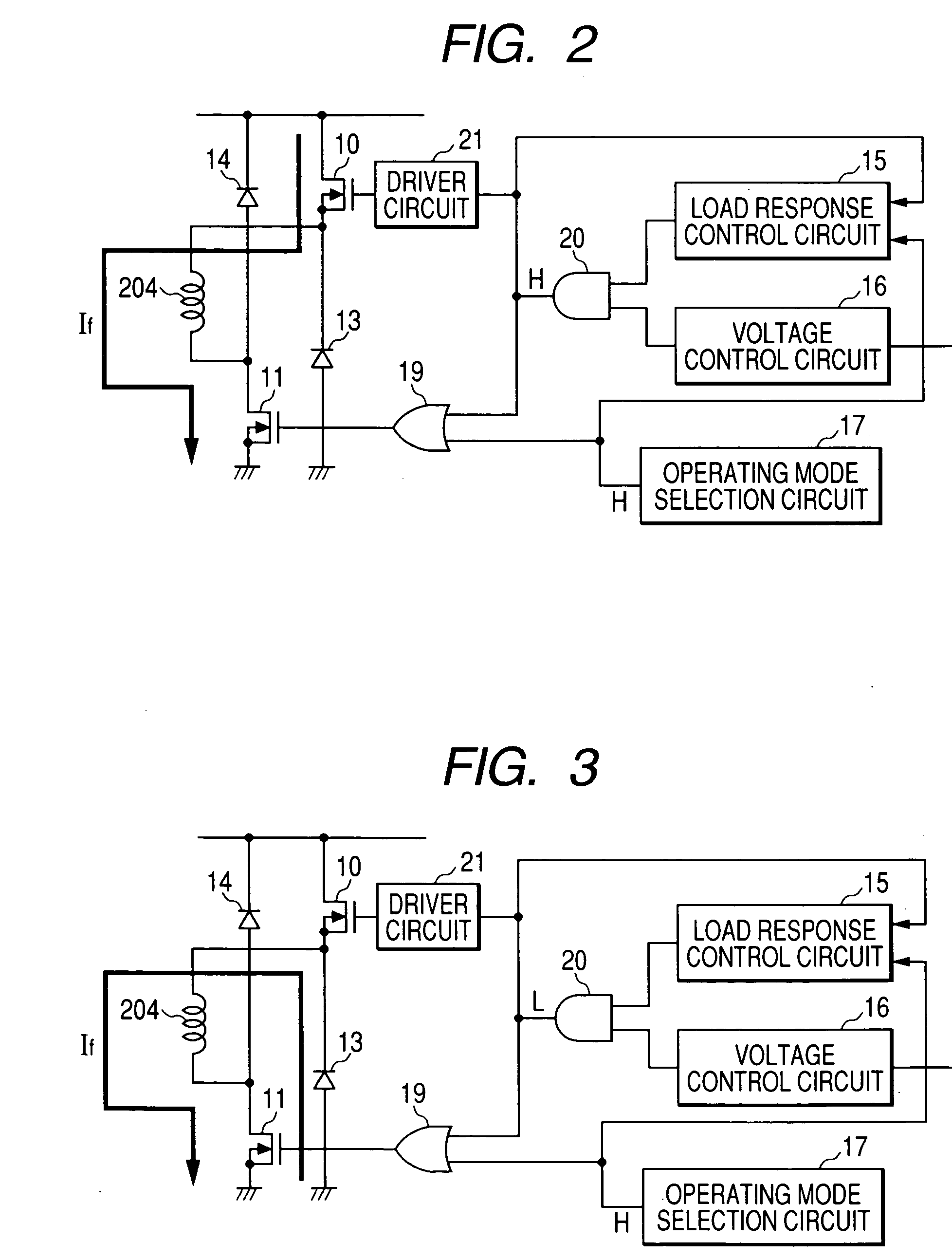
[0015] It is an objective of the present invention to overcome the disadvantages of the prior art described above, by providing an electric generator control apparatus for an electric generator of a motor vehicle whereby a regenerative current can be supplied from the field winding of the electric generator to the vehicle battery, but whereby generation of electrical (spike) noise resulting from supplying of the regenerative current is suppressed, and whereby abrupt changes in the output current of the electric generator and in the generator torque, occurring at timings of changeover to / from a regenerative current supply mode, are prevented.

Problems solved by technology

As a result, when the electric generator has a high level of available generating capacity (i.e., the vehicle engine is running at high speed) and the load on the electric generator is low, so that the battery has attained a substantially fully charged state, the battery will be incapable of absorbing the regenerative current as a charging current.
Hence, such noise spikes can damage or cause malfunctioning of the electric generator or other electronic equipment of the vehicle.
As a result, each time there is a changeover between these two modes, an abrupt change may occur in the average voltage that is applied to the field winding.
This will result in corresponding abrupt changes in the output current of the generator and in the level of generator torque (the amount of torque that must be applied by the vehicle engine to drive the rotor of the generator).
Such abrupt changes in torque are particularly undesirable, since they can result in unstable running of the vehicle engine when it is operating at low speed, e.g., when idling.

Method used


Image

  • Vehicle-mounted electric generator control system which selectively supplies regenerative field current to battery in accordance with currently available generating capacity
  • Vehicle-mounted electric generator control system which selectively supplies regenerative field current to battery in accordance with currently available generating capacity
  • Vehicle-mounted electric generator control system which selectively supplies regenerative field current to battery in accordance with currently available generating capacity

Examples


Embodiment Construction

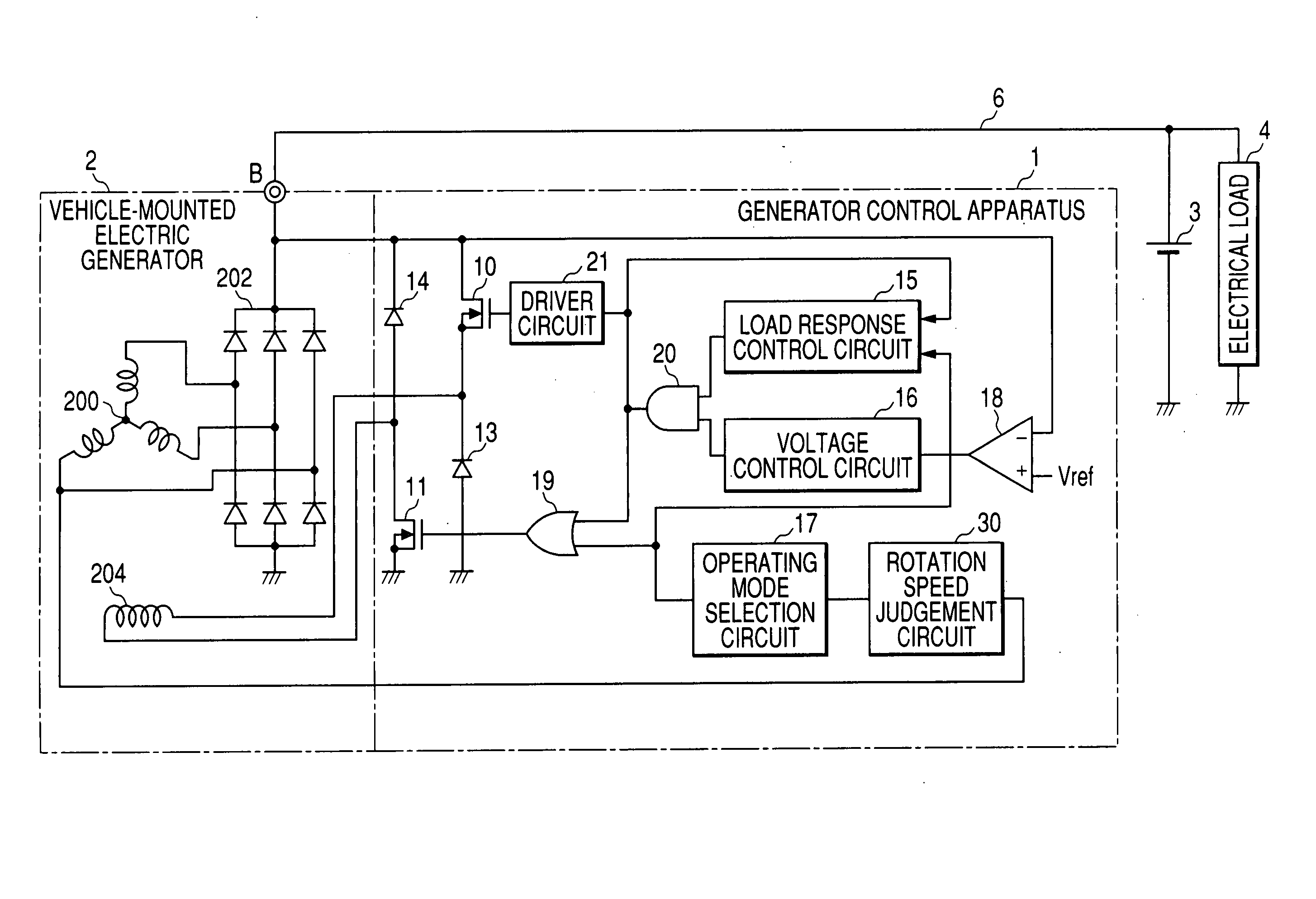
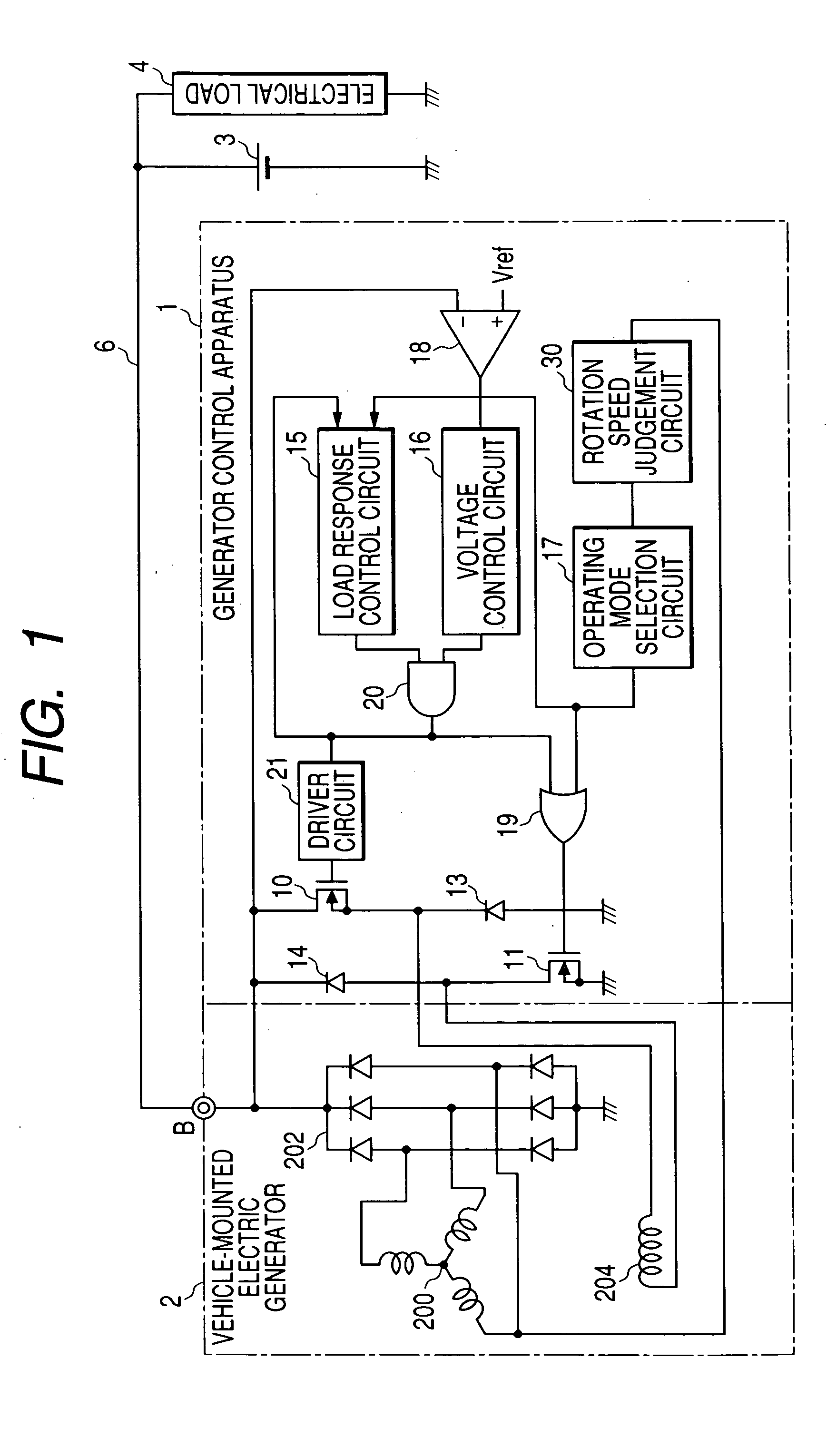
[0040] A first embodiment of a generator control apparatus will be described referring to the general system diagram of FIG. 1. This shows the connection relationships between the generator control apparatus, designated by reference numeral 1, and a vehicle-mounted electric generator (referred to in the following simply as generator) 2, a battery 3 and an electric load 4. Basically, the electric generator control apparatus 1 (referred to in the following simply as the generator control apparatus 1) applies control to the generator 2 for bringing the voltage appearing at the positive output terminal of the generator 2 (designated as the B terminal) into coincidence with an adjustment value, indicated as Vref in FIG. 1. Typically, the adjustment value is approximately 14 V.

[0041] The generator 2 is made up of a 3-phase alternator having a stator winding 200 and a rotor (not shown in the drawings) having a field winding 204 wound thereon, and a full-wave rectifier 202 which rectifies ...


PUM


Abstract

A control apparatus for a vehicle electric generator judges the currently available generating capacity of the generator and establishes a regenerative current mode of operation, utilizing an induced current of the field winding, only when the generating capacity is estimated to be below a predetermined level. The control apparatus also controls the conduction factor of a power transistor to adjust the average voltage applied to the field winding such as to prevent fluctuations in output current and generator torque that would otherwise occur at each changeover to / from the regenerative current mode.

Description

CROSS REFERENCE TO RELATED DOCUMENT [0001] This application is based on and incorporates herein by reference Japanese Patent Application No. 2004-225033 filed on Aug. 2, 2004. BACKGROUND OF THE INVENTION [0002] 1. Field of Application [0003] The present invention relates to an electric generator control apparatus for controlling the generated output of an electric generator of a motor vehicle. [0004] 2. Description of Prior Art [0005] A motor vehicle is equipped with an electric generator, typically constituted as a 3-phase alternator that is driven by the vehicle engine, in combination with a rectifier circuit, to produce a DC output voltage for charging the vehicle battery and supplying an electrical load. The level of generator output voltage is controlled by varying a duty ratio of successive on / off switching (performed by a control apparatus, i.e., regulator) of a drive voltage applied to the field winding of the alternator rotor of the electric generator (referred to in the fo...

Claims


Application Information

Patent Timeline
IPC IPC(8): H02H7/06H02P11/00H02P9/00
CPCH02J7/1446H02P9/48H02P2101/45Y02T10/92Y02T10/7005Y02T10/70
Inventor ASADA, TADATOSHI
Owner DENSO CORP
Learn More