Current-controlled oscillator

a current-controlled, oscillator technology, applied in the direction of oscillator generator, pulse generation by logic circuit, pulse technique, etc., can solve the problems of inability to compensate for process variation, low gain, or flat gain at high frequencies, etc., to achieve wide tuning range, high stability, and extended linear gain

Inactive Publication Date: 2006-02-02
INFINEON TECH AG
View PDF6 Cites 15 Cited by
  • Summary
  • Abstract
  • Description
  • Claims
  • Application Information

AI Technical Summary

Benefits of technology

[0011] The present invention provides a CCO with extended linear gain over a broad tuning range, high stability, reduced size, reduced power consumption and reduced sensitivity to process and temperature variation. These features are achieved in the present invention by utilizing a 3-stage CCO processed in a CMOS. The CCO achieves low sensitivity to process variation and linear gain over a broad frequency range by utilizing an RC / / C loading structure. The power supply rejection ratio is also improved using a power supply rejection ratio (PSRR) compensation section comprising a current source and diode electrically connected to the loading structure.

Problems solved by technology

Another problem with conventional CCO's is that the gain will drop, or become flat, at high frequencies, rather than increasing linearly, because of velocity saturation.
However, the method this paper can only provide compensation at one fixed frequency and cannot compensate for process variation.
In addition, it requires many additional circuits resulting in greater power consumption, size and cost.
31, No. 11, November 1996 by John G. Maneatis. However, this prior art CCO does not sufficiently extend the linear region of the CCO gain or minimize the process and temperature sensitivity.

Method used


Image

  • Current-controlled oscillator
  • Current-controlled oscillator
  • Current-controlled oscillator

Examples


Embodiment Construction

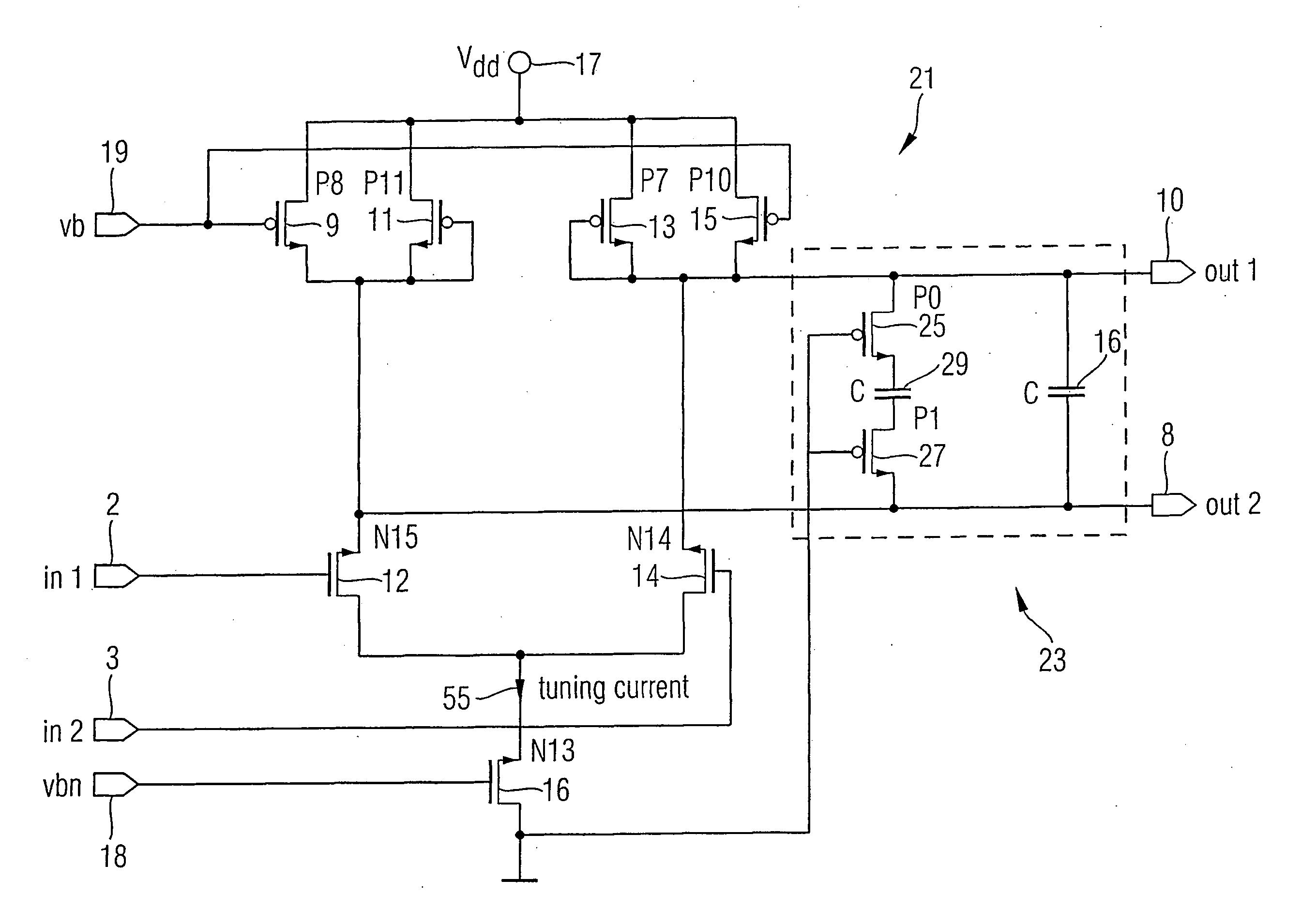
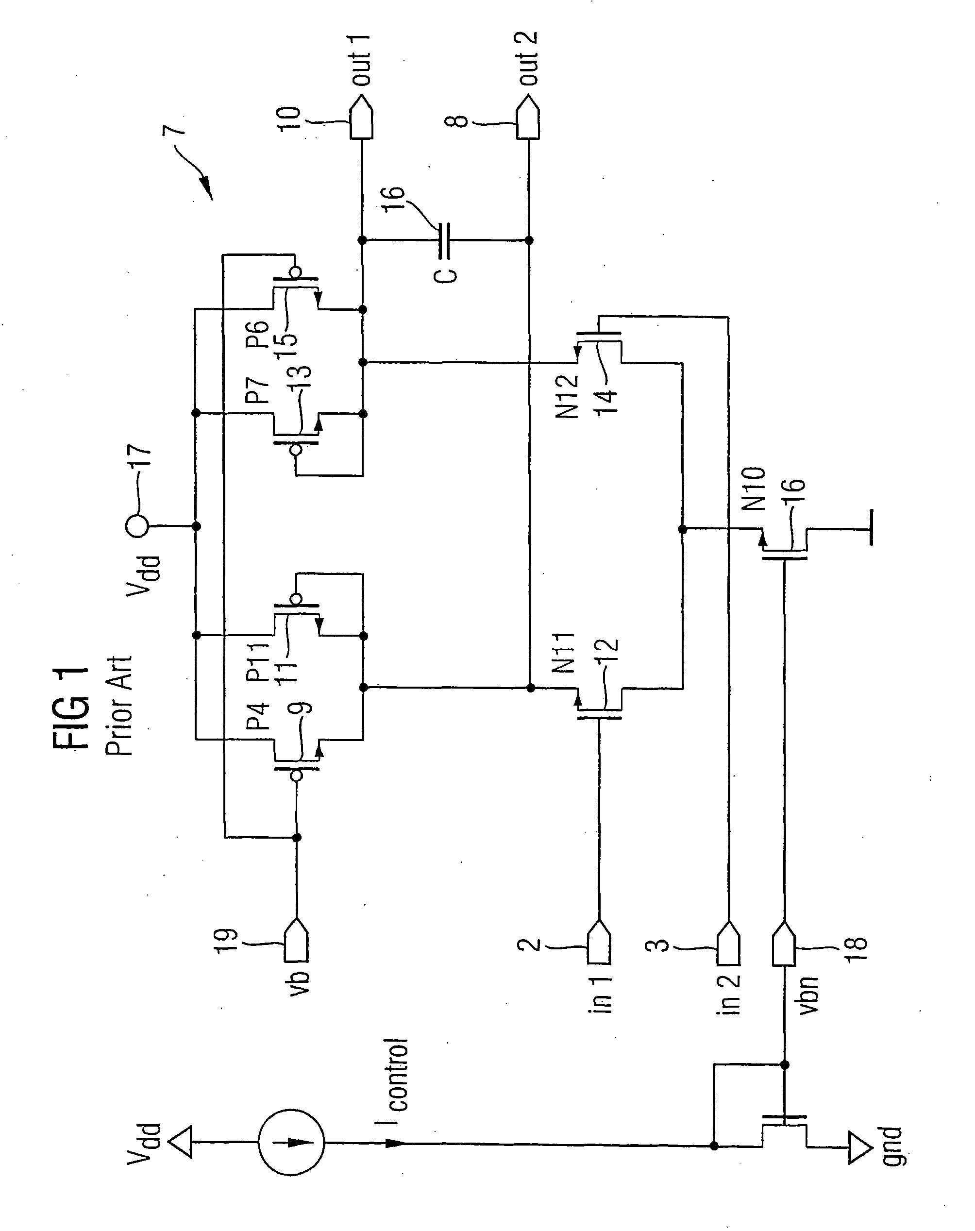
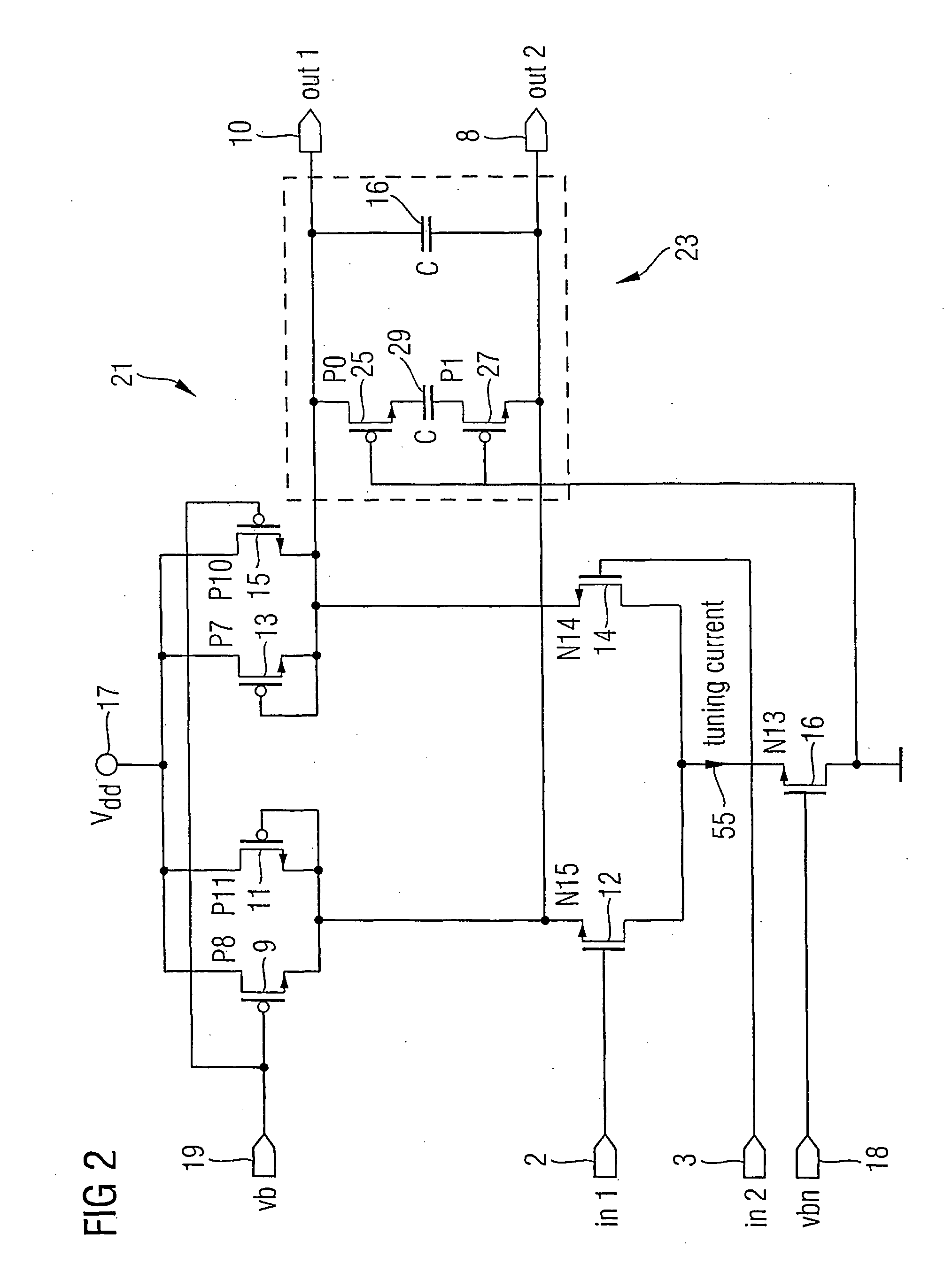
[0023]FIG. 2 illustrates a circuit 21 of a 3-stage CCO processed in a C11N digital CMOS. FIG. 9 shows the entire 3-stage CCO 51 where the circuit 21 would be positioned as the stage 53. The circuit achieves low sensitivity to process variation and linear gain over a broad frequency range by utilizing an RC / / C loading structure 23. The difference between the prior art circuit of FIG. 1 and the inventive circuit of FIG. 2 is the loading. The source of a pMOS transistor 25 is connected in series to the drain of a pMOS transistor 27 through a capacitor 29. The series connection is connected between the differential outputs 10 and 8 parallel with the capacitor 16. Both gates of the transistors 25 and 27 are tied to ground.

[0024] As compared to the CCO design of the Maneatis reference, the CCO of the present invention has a linear region of CCO gain extended by over 50% and the process and temperature sensitivity of the CCO gain is reduced by between 33% and 75% at an output frequency ra...


PUM


Abstract

The present invention provides a current controlled oscillator comprising a first section providing a first differential output and a second section providing a second differential output. A loading structure comprised of resistive and reactive elements electrically connects the first differential output with the second differential output. The resistive and reactive elements have values chosen such that the resistive elements substantially extend the linear operating frequency range of the current controlled oscillator. Transistors of the loading structure have which are tied to a power supply rejection ratio compensation section for compensating for variations in power supply voltage.

Description

FIELD OF THE INVENTION [0001] The present invention relates to current-controlled oscillators and more particularly to a low voltage 3-stage current-controlled oscillator with extended linear gain and low sensitivity to process and temperature variation. BACKGROUND OF THE INVENTION [0002] In recent years the telecommunications industry has increased its demand for improved performance from current controlled oscillators (CCO). For example, when designing phase locked loops (PLL) for frequency synthesizers and clock recovery circuits, it helps to have a CCO with linear gain to allow better modeling during system design. Better modeling during system design helps avoid possible instability problems. [0003] Additionally, it is important to reduce the CCO's power consumption and reduce the design margin. This can be achieved by designing the CCO to have low process and temperature sensitivity. [0004] Conventional 3-stage ring oscillators of the prior art can have a wide tuning range, bu...

Claims


Application Information

Patent Timeline
Patent Type & Authority Applications(United States)
IPC IPC(8): H03K3/03H03B5/20H03K3/011
CPCH03B5/20H03K3/0322H03K3/011
Inventor WU, HAI JIESUN, JING
Owner INFINEON TECH AG
Why Eureka
Try Eureka