Electronic apparatus, information processing system and method of controlling said apparatus
a technology of information processing system and electronic equipment, applied in the direction of digital output to print units, instruments, digital computers, etc., can solve the problems of inability to enable the second device, the information processing device cannot install driver software, and the device structure becomes complicated
- Summary
- Abstract
- Description
- Claims
- Application Information
AI Technical Summary
Benefits of technology
Problems solved by technology
Method used
Image

Examples
first embodiment
Modification of First Embodiment
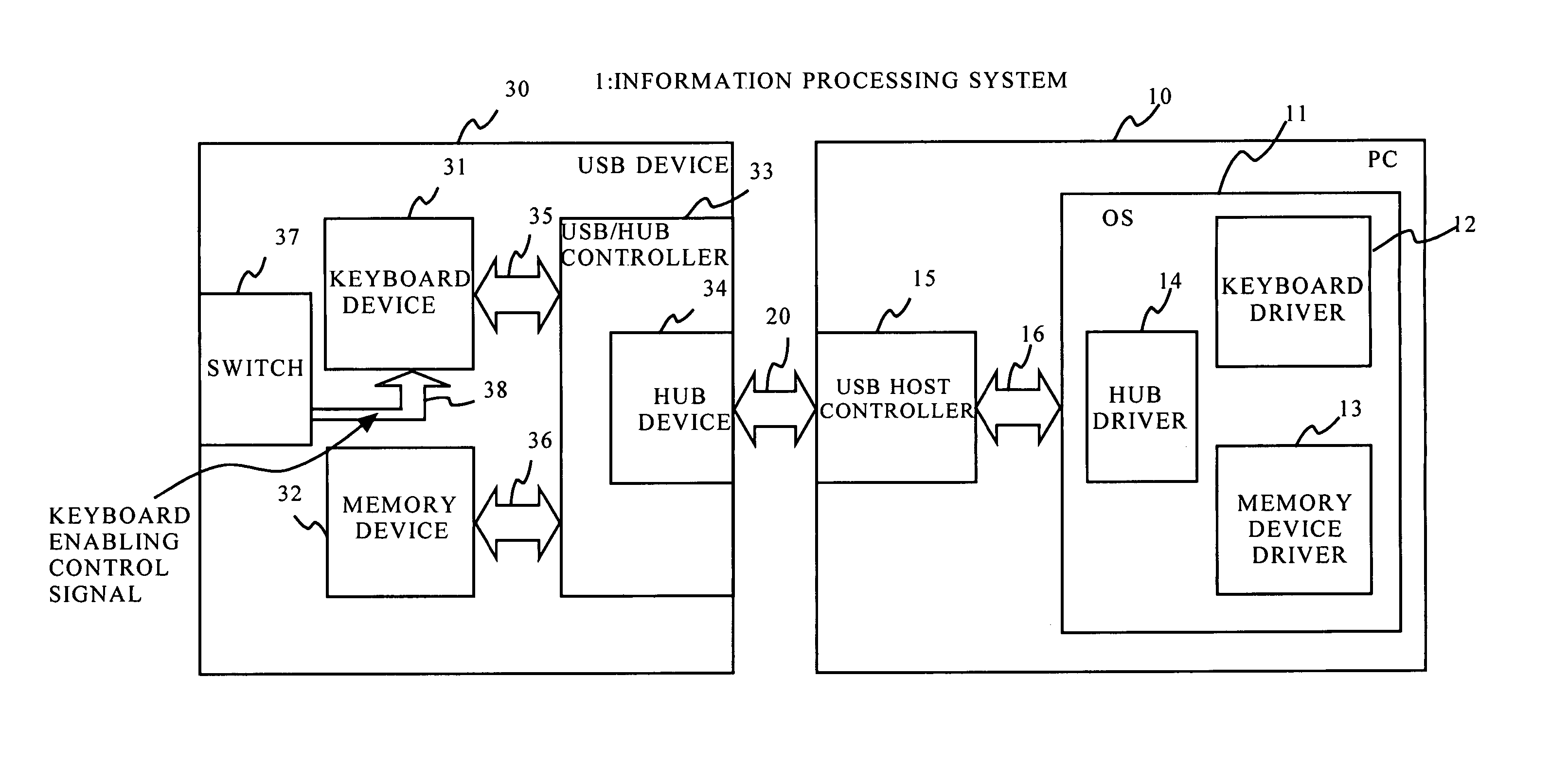
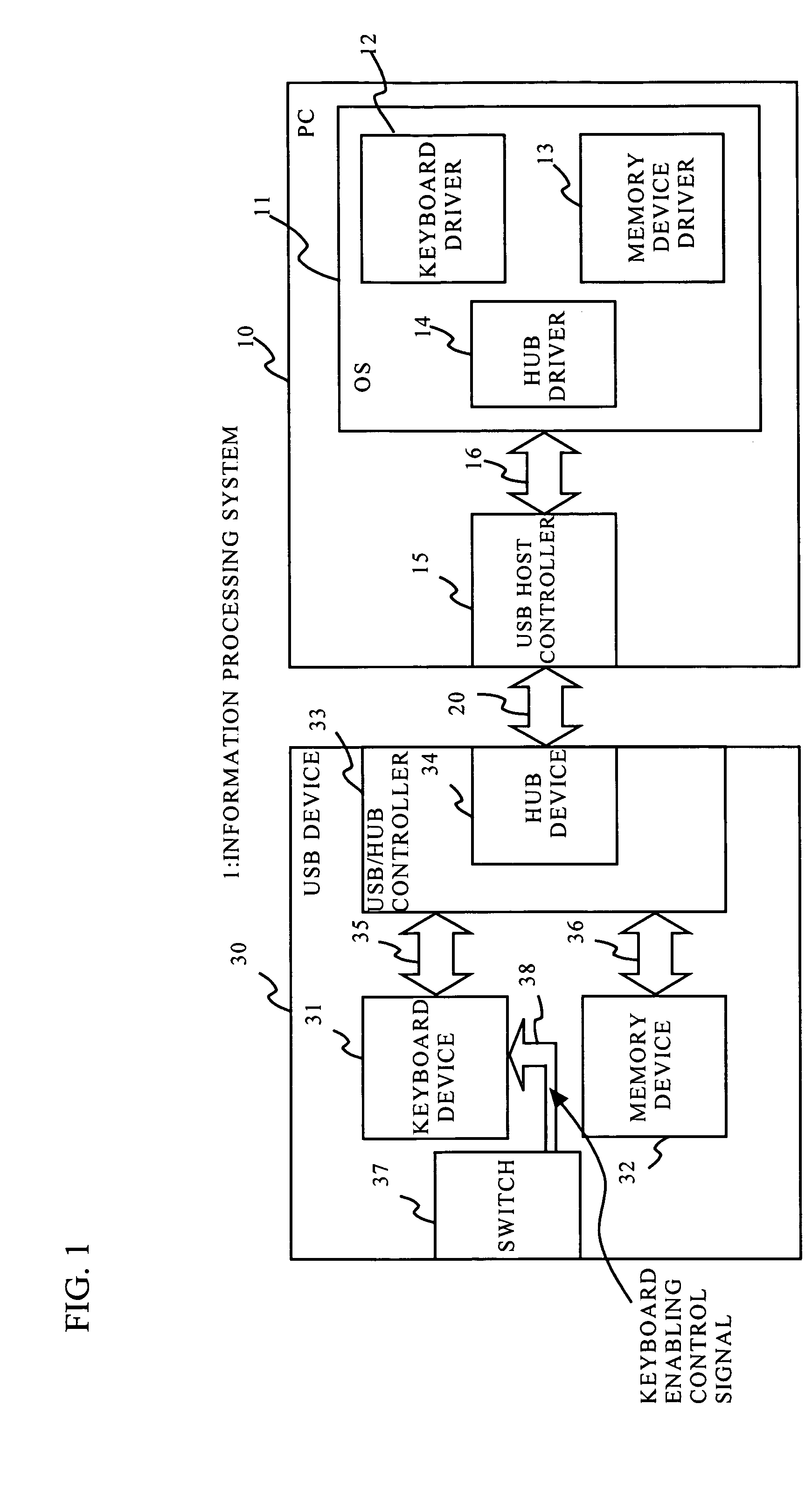
[0072] The following are other examples of the structures for switching the keyboard device 31 between the enabled state and the disabled state. The information processing system 1 shown in FIG. 8 inputs the keyboard enabling control signal 38 to the keyboard device 31 from application software 17 that operates in the PC 10. The keyboard enabling control signal 38 is transmitted as a vender request from the application software 17 to the keyboard driver 12, and from the keyboard driver 12 to the keyboard device 31, as indicated by the arrows in FIG. 8. Receiving the keyboard enabling control signal 38 output from the USB / HUB controller 33, the keyboard device 31 is switched between the enabled state and the disabled state.
[0073] The information processing system 1 shown in FIG. 9 has a RFID (Radio Frequency Identification) device 50 incorporated into the USB device 30. An external RFID write device 51 sets the RFID device 50 of the USB device 30 to t...
second embodiment
[0083] Next, a second embodiment of the present invention is described. The USB device 30 of this embodiment includes a multi function controller 40, as shown in FIG. 12. The multi function controller 40 includes a keyboard device 41 and a memory device 42. The keyboard device 41 and the memory device 42 exist as a physical device in the multi function controller 40. The keyboard device 41 and the memory device 42 are connected to the USB host controller 15 via the USB cable 20.
[0084] The multi function controller 40 and the switch 37 are connected to each other with a special signal line. The switch 37 is connected to the general input / output terminal or the external interrupt terminal of the multi function controller 40. The keyboard enabling control signal 38 transmitted from the switch 37 is stored in the memory status in a RAM 44 of the multi function controller 40. The keyboard device 41 analyzes the keyboard enabling control signal 38 stored in the RAM 44 through a data anal...
third embodiment
[0090] Next, a third embodiment of the present invention is described. FIG. 16 illustrates the structure of this embodiment. In this embodiment, the keyboard enabling control signal 38 from the switch 37 is also stored in the RAM 44. The keyboard device 41 analyzes the keyboard enabling control signal 38 stored in the RAM 44 with the data analysis engine 413, and switches between the enabled state and the disabled state. Likewise, the memory device 42 also analyzes the keyboard enabling control signal 38 stored in the RAM 44 with the data analysis engine 423, and switches between the enabled state and the disabled state. When the keyboard device 41 is put into the enabled state by the keyboard enabling control signal 38, the memory device 42 is put into the disabled state by a memory device disabling control signal 47.
[0091] Referring now to the flowcharts of FIGS. 17A through 19B, the operation of this embodiment is described in detail. FIG. 17A shows the operation sequence of the...
PUM
 Abstract
Description
Claims
Application Information
 - R&D
- Intellectual Property
- Life Sciences
- Materials
- Tech Scout
- Unparalleled Data Quality
- Higher Quality Content
- 60% Fewer Hallucinations
Browse by: Latest US Patents, China's latest patents, Technical Efficacy Thesaurus, Application Domain, Technology Topic, Popular Technical Reports.
© 2025 PatSnap. All rights reserved.Legal|Privacy policy|Modern Slavery Act Transparency Statement|Sitemap|About US| Contact US: help@patsnap.com