Optical systems including wavefront correcting optical surfaces

a wavefront correction and optical surface technology, applied in the field of optical systems, can solve the problems of thermal drift, negative effects on linewidth and center wavelength of the laser, and unsatisfactory optical elements of the laser, so as to improve the performance of the optical system, improve the performance, and improve the effect of stability

Inactive Publication Date: 2006-02-02
CORNING INC
View PDF9 Cites 10 Cited by
  • Summary
  • Abstract
  • Description
  • Claims
  • Application Information

AI Technical Summary

Benefits of technology

[0009] Another aspect of the present invention relates to method of making an optical system including the steps of selecting a plurality of optical elements for the optical system; selecting a configuration for the optical system; determining the performance of the optical system comprising the selected optical elements in the selected configuration; ensuring that at least one of the optical elements is a refractive optical element having a wavefront correcting optical surface adapted to improve the performance of the optical system; and assembling the optical elements into the optical system having the selected configuration.
[0010] The optical systems and methods of making optical systems of the present invention result in a number of advantages over conventional optical systems and methods. For example, the optical systems of the present invention can have improved performance, and can be adapted to provide a desired wavefront profile. Both static wavefront errors (caused by imperfections in the optical components of the system as made), and dynamic wavefront errors (caused by the hot state distortion of the optical components from their as-made geometries) can be minimized, not only for particular optical elements, but also for the system as a whole. The optical systems of the present invention can be made without actively adjustable elements such as adaptive optics or bendable gratings, and can therefore have relatively high stability and low cost. Additional features and advantages of the invention will be set forth in the detailed description which follows, and in part will be readily apparent to those skilled in the art from the description or recognized by practicing the invention as described in the written description and claims hereof, as well as in the appended drawings.

Problems solved by technology

The optical elements of the laser are generally not ideal, due, for example, to manufacturing and material limitations.
For example, the linewidth and center wavelength of the laser can be negatively affected when the beam propagating inside the laser has a change in wavefront profile.
This thermal drift can be especially problematic in high power UV lasers, which use CaF2 optical elements.
While this approach can be effective, such actively adjustable elements can be very expensive, require complicated driving mechanisms, and can be difficult to combine with the rest of the stringently engineered laser architecture.
Further, such actively adjustable elements can tend to increase the risk of failure and instability, and may not be able to sufficiently correct static and dynamic wavefront errors in the laser.

Method used


Image

  • Optical systems including wavefront correcting optical surfaces
  • Optical systems including wavefront correcting optical surfaces
  • Optical systems including wavefront correcting optical surfaces

Examples


Embodiment Construction

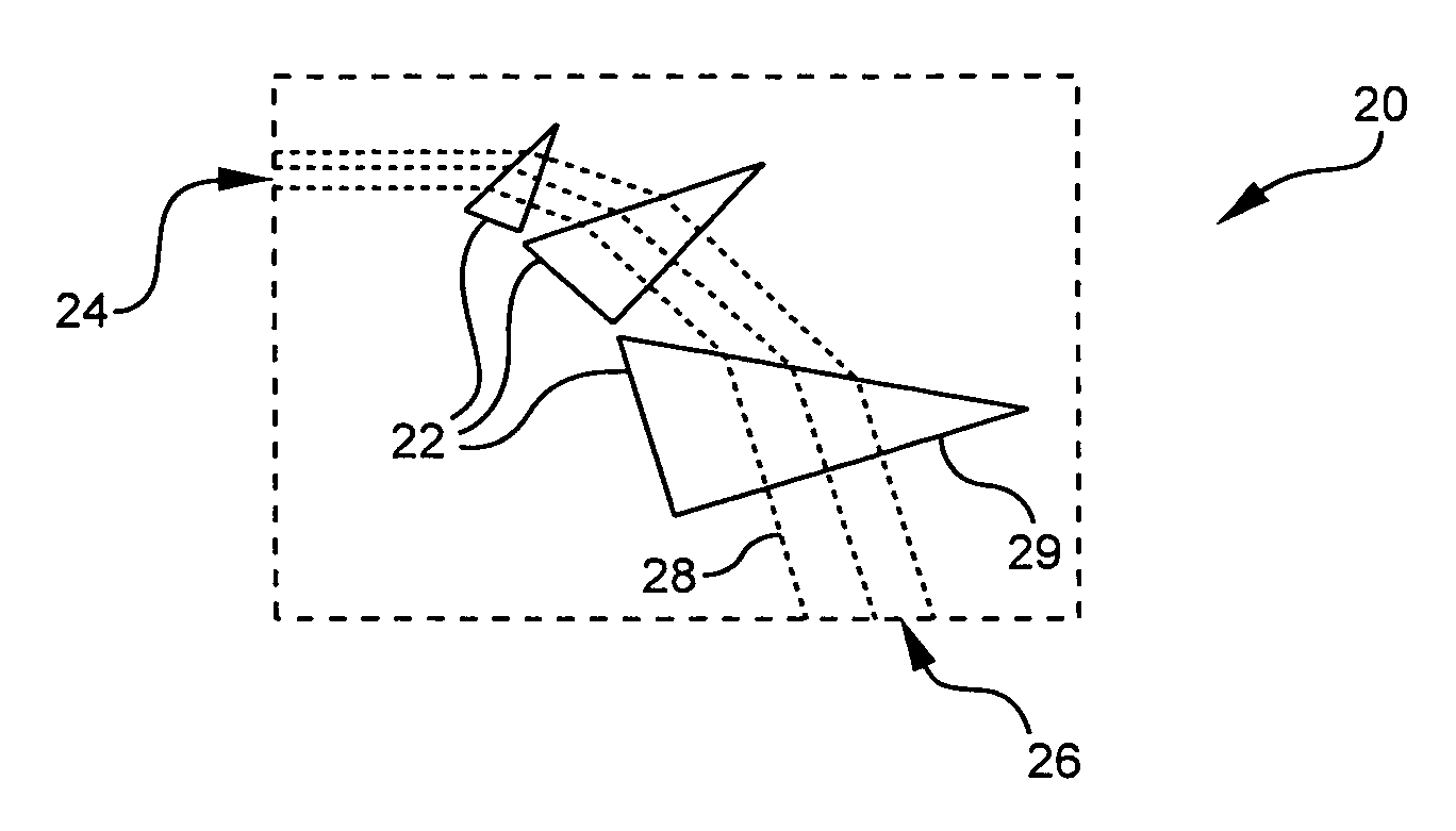
[0022] One embodiment of the present invention is shown in schematic view in FIG. 1. A beam expanding assembly 20 has a set of one or more prisms 22, an input 24, an output 26 and beam path 28. The set of one or more prisms is configured to expand a beam propagating from input 24 along the beam path 28 to output 26. At least one of the set of prisms has a wavefront correcting optical surface 29 which is substantially non-planar when the line-narrowing module is in a cold state. As used herein, an optical surface is a prism surface through which a beam is transmitted along the beam path. A wavefront correcting optical surface may be formed on only one of the optical surfaces of one of the prisms, or wavefront correcting optical surfaces may be formed on multiple optical surfaces of the set of prisms.

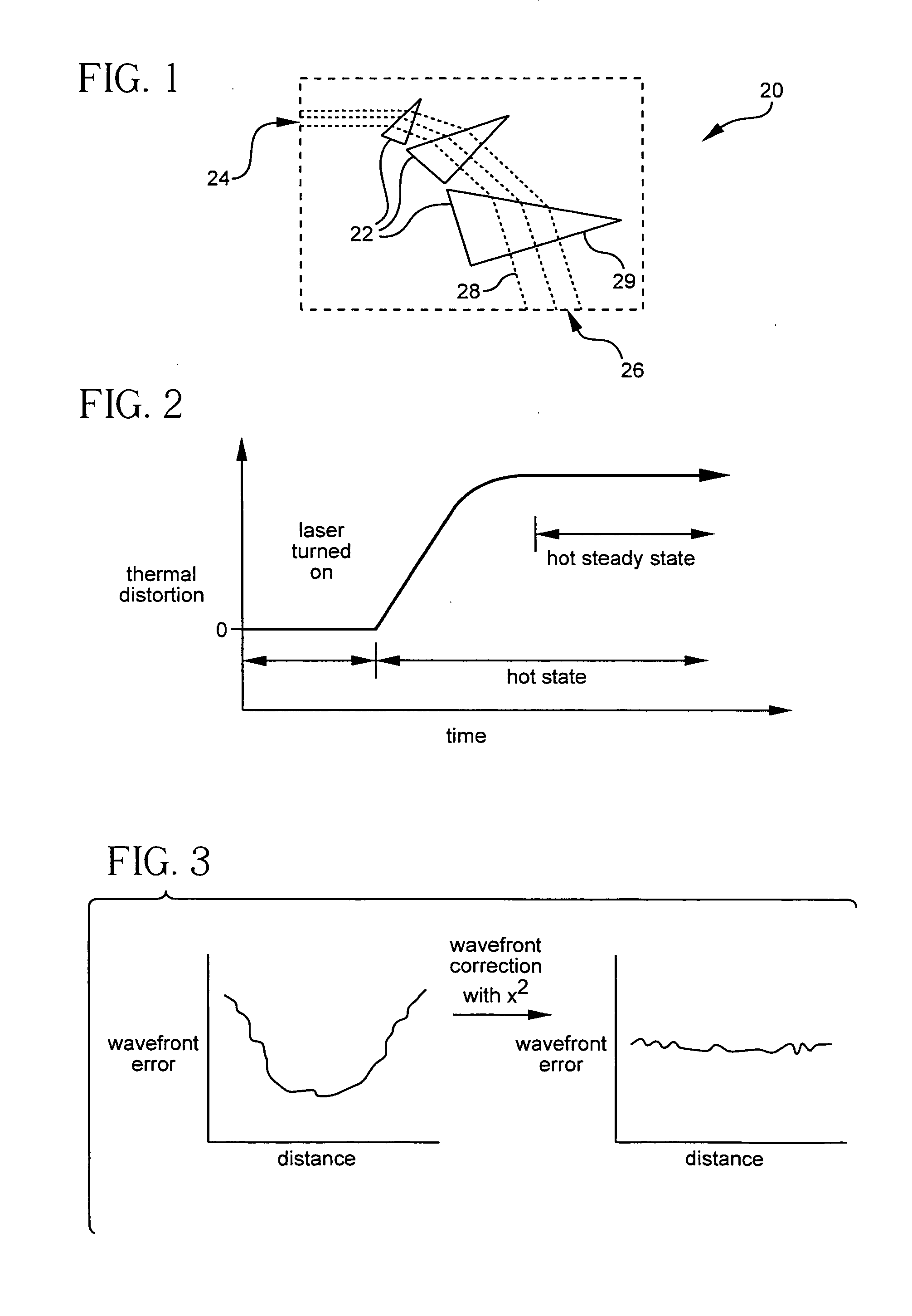
[0023]FIG. 2 is a diagram illustrating a cold state, a hot state, and a hot steady state. As used herein, a device is in a cold state when it is not being used, and at thermal equilibriu...


PUM


Abstract

The present invention relates to optical systems, beam expanding assemblies, line narrowing modules, and lasers having refractive optical elements with wavefront correcting optical surfaces. The present invention enables the skilled artisan to provide optical systems, beam expanding assemblies, line narrowing modules, and lasers having improved optical properties, such as, in the case of lasers, narrow linewidth at high power, and substantially planar wavefronts.

Description

BACKGROUND OF THE INVENTION [0001] 1. Field of the Invention [0002] The present invention relates generally to optical systems, and more particularly to beam expanding assemblies, line narrowing modules, lasers, and other optical systems having desirable beam wavefront characteristics. [0003] 2. Technical Background [0004] For many applications, optical systems that provide beams of radiation having specified wavefront properties are highly desired. For example, in the UV photolithography processes used to make semiconductor devices such as computer chips, a substantially planar wavefront is highly desirable in order reduce interferometric effects and to achieve the best possible photolithographic performance. Further, the performace of the UV lasers used in these photolithographic processes is dependent on the wavefront characteristics of the beam propagating inside the laser, which are in turn dependent on the optical elements of the laser. The optical elements of the laser are ge...

Claims


Application Information

Patent Timeline
Patent Type & Authority Applications(United States)
IPC IPC(8): G03H1/08
CPCG02B7/008G02B7/181G02B27/0972G02B27/0911G02B27/0025
Inventor CLAR, COLLEEN R.SCHREIBER, HORST
Owner CORNING INC
Why Eureka
Try Eureka