Head gimbal assemblies for very low flying height heads with optional micro-actuators in a hard disk drive

Inactive Publication Date: 2006-02-02
SAMSUNG ELECTRONICS CO LTD
View PDF3 Cites 58 Cited by
  • Summary
  • Abstract
  • Description
  • Claims
  • Application Information

AI Technical Summary

Benefits of technology

[0019] The present invention includes a head gimbal assembly, which may include a piezo layer mechanically coupled with the slider. The bending of the piezo layer alters the flying height of the read-write head of th

Problems solved by technology

When a voltage difference is applied across the leads, the piezoelectric effect causes the piezo

Method used


Image

  • Head gimbal assemblies for very low flying height heads with optional micro-actuators in a hard disk drive
  • Head gimbal assemblies for very low flying height heads with optional micro-actuators in a hard disk drive
  • Head gimbal assemblies for very low flying height heads with optional micro-actuators in a hard disk drive

Examples


Example

[0047] The following description is provided to enable any person skilled in the art to make and use the invention and sets forth the best modes presently contemplated by the inventors for carrying out the invention. Various modifications, however, will remain readily apparent to those skilled in the art, since the generic principles of the present invention have been defined herein.

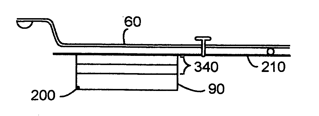
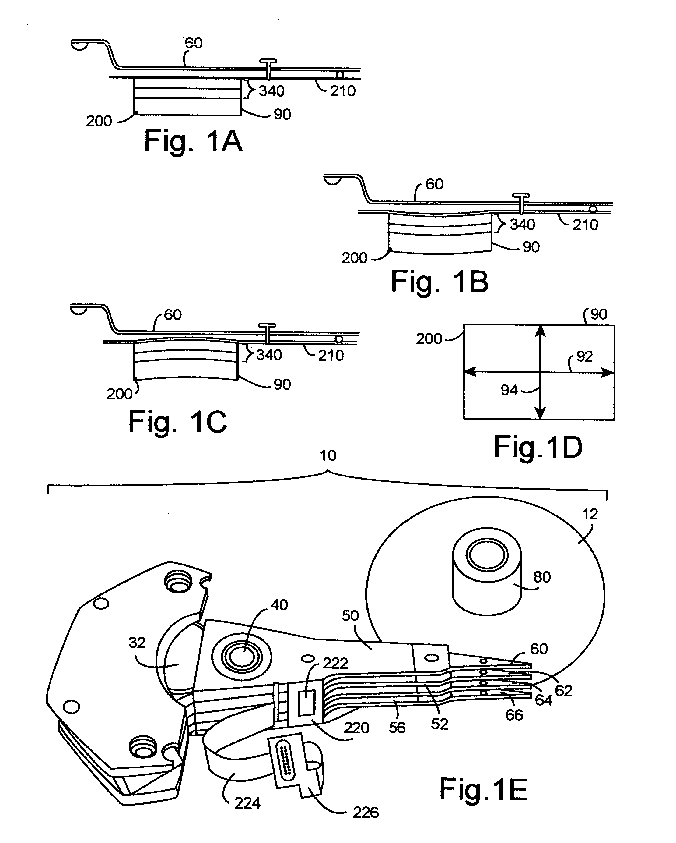
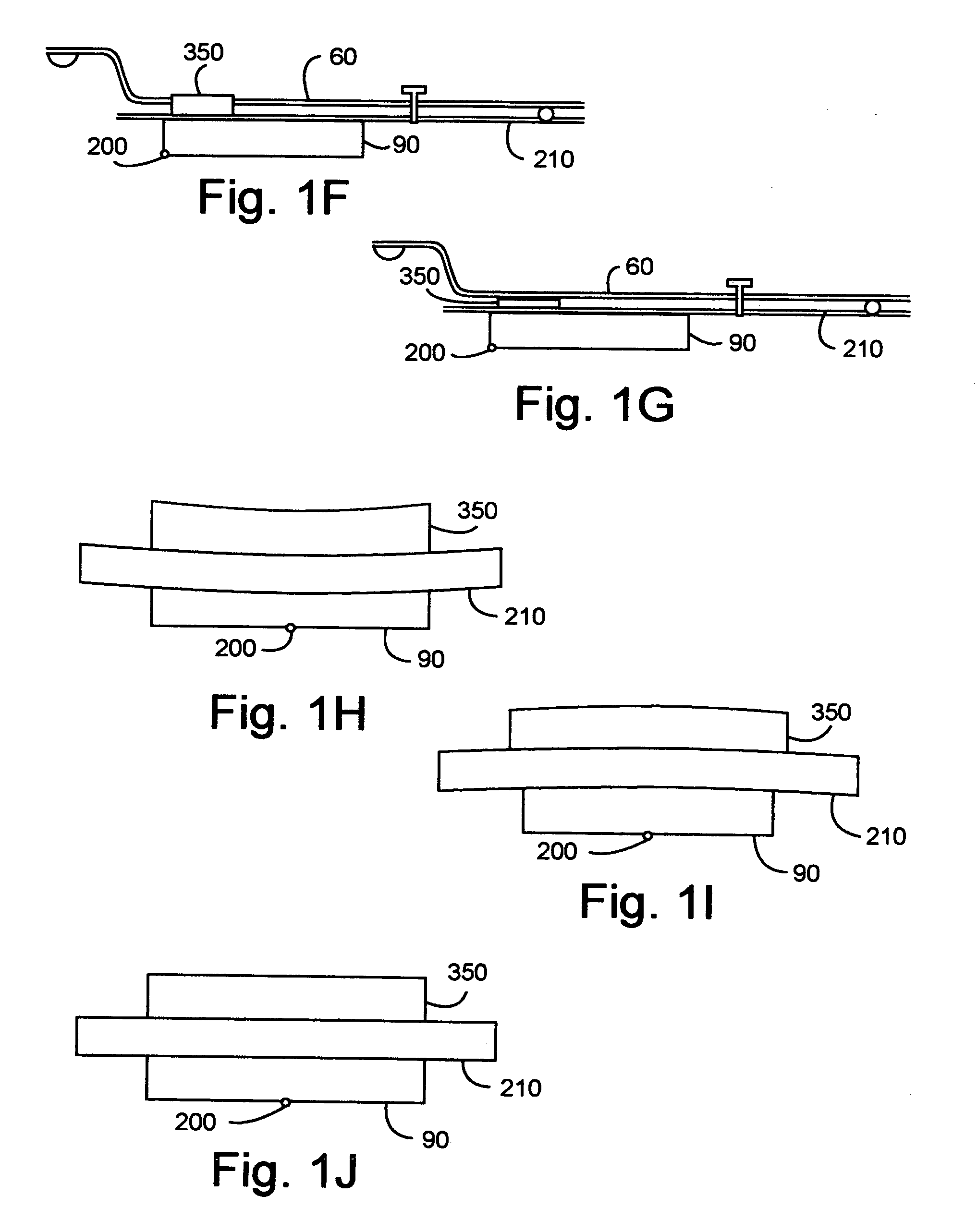
[0048] The invention may include head gimbal assemblies 60 as shown in FIGS. 1A-1C including a piezo layer 340 mechanically coupled to a slider 90. The read-write head 200 is embedded into a surface of the slider 90.

[0049]FIG. 1D shows a cross section of the slider 90 of FIGS. 1A-1C, with an alternative position of the read-write head 200. The crown of the slider refers to the curvature about the major axis 92 of the slider. The camber of the slider refers to the curvature about the minor axis 94 of the slider.

[0050]FIG. 1A shows the head gimbal assembly 60 with the piezo layer 340 in a neutral state,...


PUM

PropertyMeasurementUnit
Electric potential / voltageaaaaaaaaaa
Heightaaaaaaaaaa

Abstract

A head gimbal assembly may include a piezo layer mechanically coupled with the slider. Bending the piezo layer alters flying height. Alternatively, it may include a piezo element mechanically coupled by a flexure to the slider top near the read-write head, which when excited, bends the flexure to alter the flying height. A bridge flex circuit is included, providing a piezo-control bundle to at least one of the piezo layer leads. The flex circuit assembly may further provide a piezo control bundle, shared with the piezo control bundles for multiple read-write heads. The head gimbal assembly may include a micro-actuator to position the read-write head near a track on the accessed, rotating disk surface. The flex circuit assembly may provide a source control bundle, shared with micro-actuator control bundles for multiple read-write heads. When accessing, all micro-actuators perform the same positioning action, insuring proper positioning of the read-write head. This applies to co-located and non co-located micro-actuators. Wire bundles may include one or two active signal wires. Voice coil actuators and the hard disk drives, as well as making these, are included.

Description

BACKGROUND OF THE INVENTION [0001] 1. Field of the Invention [0002] The present invention relates to head gimbal assemblies in a hard disk drive. [0003] 2. Background Information [0004] Modern disk drives include a servo controller driving a voice coil actuator to position a read-write head near a track on a rotating disk surface. The read-write head communicates with the servo controller, providing feedback, which is used in controlling the read-write head's positioning near the track. The read-write head is embedded in a slider, which floats on a thin air bearing a very short distance above the rotating disk surface. [0005] The trend in the hard disk drive industry is to increase the areal density of the rotating disk surfaces. This is usually achieved by decreasing the flying height of the read-write head above the rotating disk surface. Currently, read-write heads fly at 10 nano-meters (nm) from the rotating disk surfaces. [0006] There are problems with flying the read-write hea...

Claims


Application Information

Patent Timeline
IPC IPC(8): G11B21/02G11B5/54G11B5/127
CPCG11B5/4826G11B5/4853Y10T29/49025G11B5/5552G11B5/58G11B5/486G11B21/02G11B21/21
Inventor SHARMA, VINODKWON, HAESUNGLEE, HYUNG JAI
Owner SAMSUNG ELECTRONICS CO LTD
Why Eureka
Try Eureka