
Protective coating for oxide ceramic based composites

a ceramic and composite material technology, applied in the field of ceramic composite materials, can solve the problems of particle-particle bond weakening, gas turbine engine high temperature, surface recession, etc., and achieve the effect of improving strain accommodation

Inactive Publication Date: 2006-02-02
HONEYWELL INT INC
View PDF20 Cites 45 Cited by
  • Summary
  • Abstract
  • Description
  • Claims
  • Application Information

AI Technical Summary

Benefits of technology

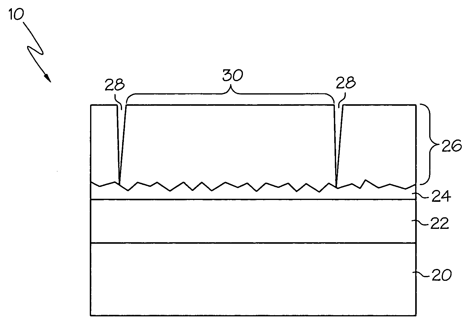
The present invention provides a layered structure for gas turbine engine components such as combustion chamber liners. The structure includes a substrate, a first layer of oxide / oxide composite material, and a second layer with greater porosity and tolerance to water vapor. The first layer is made of materials such as alumina or rare earth monosilicates and has a thickness ranging between 1 and 10 mills. The second layer has a porous compliant microstructure with segmentation gaps for enhanced strain accommodation and is made of materials such as stabilized zirconia or hafnia. The method of manufacturing the structure includes depositing the first layer using plasma spraying or slurry deposition, and depositing the second layer using plasma spraying or electron beam—physical vapor deposition. The layered structure provides improved properties such as enhanced strain accommodation and resistance to water vapor damage.

Problems solved by technology

Gas turbine engines are subjected to high temperatures during operation and consequently include components made from insulative materials.
Volatile hydroxides can cause surface recession and particle-particle bond weakening within the base composite.
An uninhibited water vapor attack can eventually cause a combustion liner or other component made of an oxide / oxide composite to lose some of its thickness and strength.

Method used


Image

  • Protective coating for oxide ceramic based composites
  • Protective coating for oxide ceramic based composites

Examples


Embodiment Construction

[0012] The following detailed description of the invention is merely exemplary in nature and is not intended to limit the invention or the application and uses of the invention. Furthermore, there is no intention to be bound by any theory presented in the preceding background of the invention or the following detailed description of the invention.

[0013] The present invention is a multi-layered thermal and chemical barrier coating system that includes materials that are able to insulate a base material such as a ceramic material. The system materials also provide a seal over the base material that protects the base material from unwanted penetration of chemicals such as salt compounds and water vapor. Since the coating materials reduce the temperature of the air-cooled substrate and shield the porous composite substrate from permeation of combustion derived water vapor, the coated composite system is useful to manufacture turbine engine components and other similar articles.

[0014]F...


PUM

PropertyMeasurementUnit
porosityaaaaaaaaaa
thicknessaaaaaaaaaa
temperatureaaaaaaaaaa

Abstract

A layered structure includes a substrate comprising a layer of an oxide / oxide ceramic based composite material, a first oxide layer disposed directly on the substrate and formed from a material that has no greater than about 10% porosity and is substantially impermeable by water vapor, and a second oxide layer disposed directly on the first oxide layer and having a greater porosity than the first oxide layer. Either or both the first and second oxide layers of the coating system may be deposited using a plasma spraying process, a slurry deposition process which is followed by a sintering step, or an EB-PVD process.

Description

TECHNICAL FIELD [0001] The present invention relates to gas turbine engines and, more particularly, to ceramic composite materials that are useful for manufacturing engine components. BACKGROUND [0002] Gas turbine engines are subjected to high temperatures during operation and consequently include components made from insulative materials. A porous oxide / oxide composite is one example of a high temperature insulative structural material used for a gas turbine engine component such as a combustion liner. One type of oxide / oxide composite that can be readily used in a combustion liner consists of alumina fibers embedded in an alumina matrix. Since this composite may weaken or degrade at temperatures in excess of 2200° F., one or more layers of a high temperature porous insulation material, typically a more or less friable oxide-ceramic based material such as alumina, are commonly used to provide a thermal barrier layer on top of the structural ceramic composite. [0003] Since the oxide...

Claims


Application Information

Patent Timeline
Patent Type & Authority Applications(United States)
IPC IPC(8): B32B19/00
CPCC04B41/009Y10T428/12535C04B41/89C04B41/52Y10T428/12611C04B41/4582C04B41/5031C04B41/5035C04B41/522C04B41/5037C04B41/4527C04B41/5045C04B41/5024C04B41/5042C04B35/01C04B35/10C04B35/803Y10T428/249956
Inventor STRANGMAN, THOMAS E.SCHENK, BJOERNYANKOWICH, PAUL R.
Owner HONEYWELL INT INC
Learn More