
Ozone-assisted lithography process with image enhancement for CPP head manufacturing

Inactive Publication Date: 2006-02-02
HEADWAY TECH INC +1
View PDF6 Cites 4 Cited by
  • Summary
  • Abstract
  • Description
  • Claims
  • Application Information

AI Technical Summary

Benefits of technology

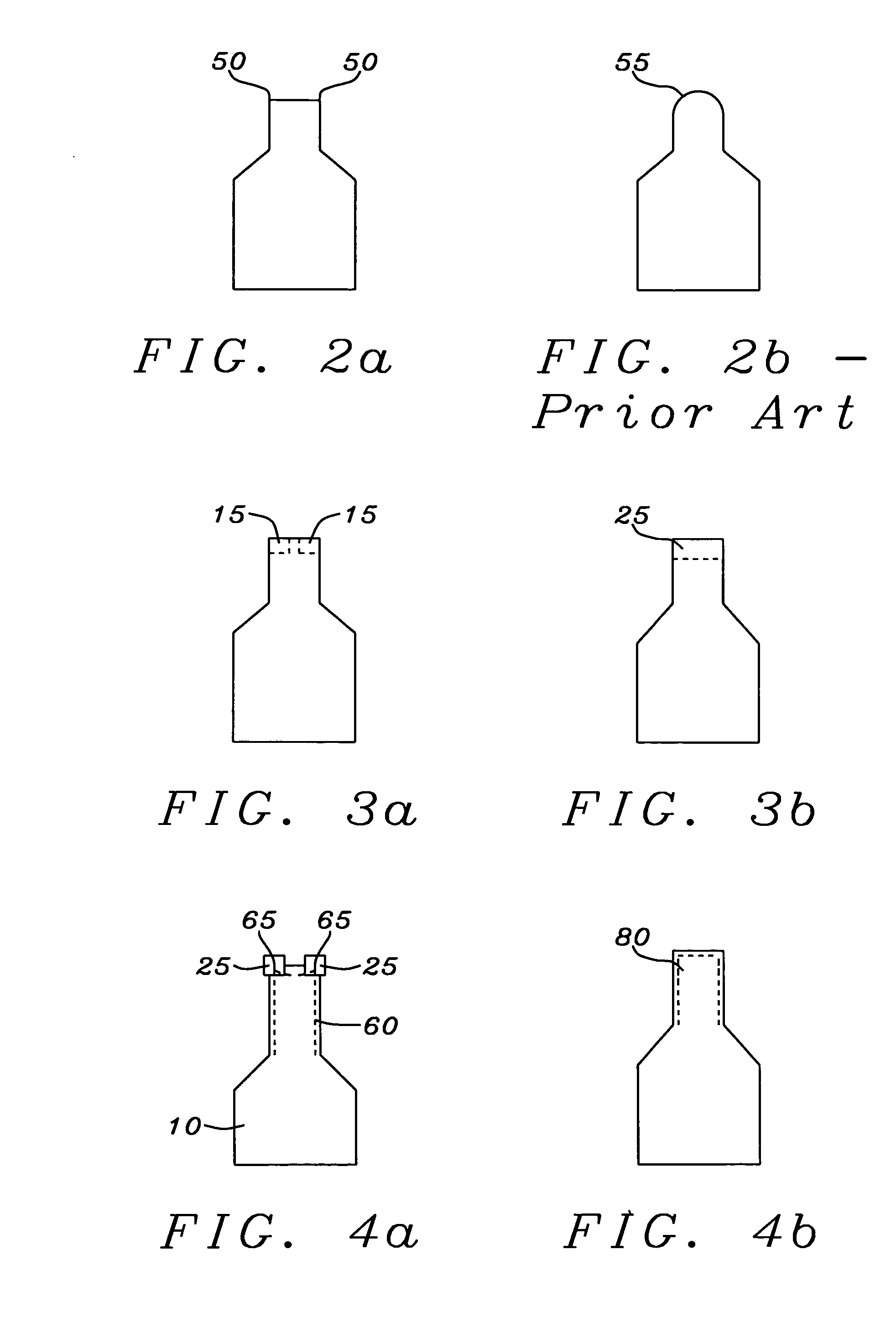
[0013] In accord with the object of this invention there is provided a bi-layer lift-off mask and a method of forming the mask on a substrate which is preferably a GMR stack. The upper layer of the mask (the stencil or image-forming layer) has, in an overhead perspective, a narrow extending portion with sharply defined edges and corners, yet the exposure and development of the mask retains the edge and corner definition without rounding and without the loss of a supporting underlayer. The upper layer of the bi-layer structure is formed of a photoresist material (or a material which can be exposed by appropriate radiation and developed) and the lower layer is formed of a PMGI polymer. The corner regions of the mask, which in prior art formation were subject to either elimination by rounding off or to formation with no underlayer support, are now augmented by auxiliary pattern pieces as shown in FIG. 4a. Referring to FIG. 4a, there is seen, in a schematic overhead view, the primary stencil mask (10), with two auxiliary pattern pieces formed on its corners (35). The auxiliary pattern pieces are formed by differentially exposing the patterned portions of the upper layer relative to the primary mask, as will be discussed below. A first development process, using TMAH (tetramethyl ammonium hydroxide) developing solution, undercuts the lower PMGI layer as shown in dashed outline (60). The TMAH, if used by itself, dissolves the PMGI too rapidly to be used to form the mask in its final form. It is during this TMAH part of the process that the auxiliary pattern pieces prevent excessive undercutting of the PMGI at the corner regions (65). A second, ozone oxidation process, the results of which are shown in FIG. 4b, removes the auxiliary pattern pieces, that have already performed their part of the process, and controllably forms the defined pattern edges and corners (shown encircled). The dashed outline (80) shows the periphery of the controllably undercut underlayer, which now provides adequate support for the edge and corner regions of the upper mask portion. The differential etching of the lower layer is therefore accomplished by a novel method combining the use of selected organic photoresistive materials for the mask layers, an initial dissolution of the lower mask layer by an organic solvent, such as a 1.79% solution of TMAH, followed by a precisely controlled ozone oxidation process (without the TMAH) at an elevated processing temperature to create the final shape. It is noted that the use of TMAH alone produces an etch rate that is too high for the controlled thinning necessary to produce the ridge. On the other hand, using anisotropic plasma etches, such as oxygen plasma etches, to remove the lower layer, would damage the upper layer of the mask. Thus, the combination of the initial use of TMAH alone, and the subsequent ozone oxidation produces the required control of the etch process that allows the objects of the invention to be achieved.

Problems solved by technology

It is noted that the use of TMAH alone produces an etch rate that is too high for the controlled thinning necessary to produce the ridge.
On the other hand, using anisotropic plasma etches, such as oxygen plasma etches, to remove the lower layer, would damage the upper layer of the mask.

Method used


Image

  • Ozone-assisted lithography process with image enhancement for CPP head manufacturing
  • Ozone-assisted lithography process with image enhancement for CPP head manufacturing
  • Ozone-assisted lithography process with image enhancement for CPP head manufacturing

Examples


Embodiment Construction

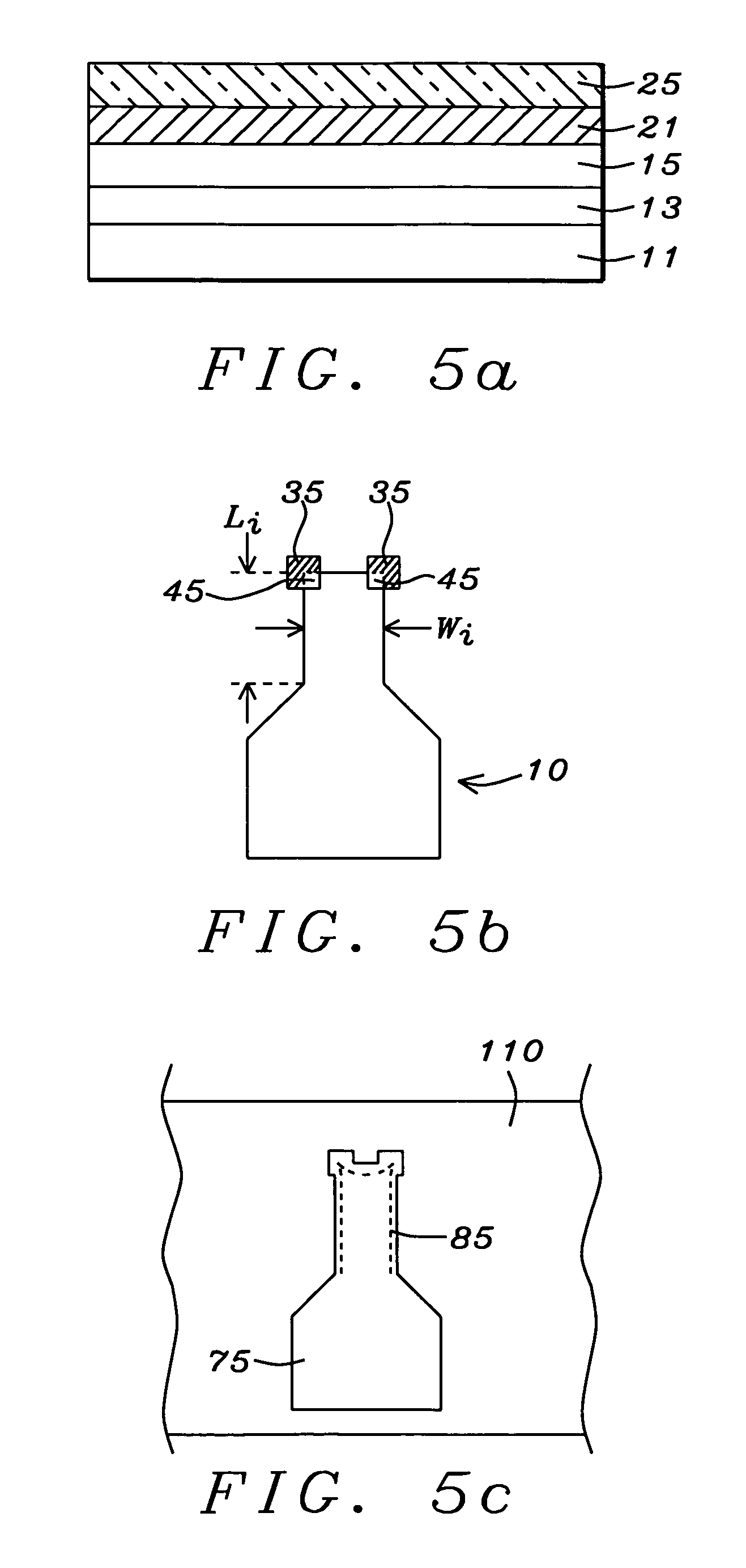
[0021] The present invention provides a method of forming and using a photolithographic bi-layer lift-off mask of sub-100 nm (less than 0.1 microns) critical dimensions, having sharply defined edges and corner regions. The mask has an upper, stencil portion formed of a photoresistive material, which is commercially available NEB22A2 in this embodiment but which could be an alternative material that is sensitive to other forms of exposing radiation. The mask has a lower, undercut portion, formed of PMGI. The edge and corner regions of the mask are formed and shaped by a process that involves adding auxiliary pattern pieces to the corners, which prevent excessive undercutting of the PMGI during a first development process, then removing those auxiliary pieces and completing the formation of the stencil and PMGI layers using a process of ozone oxidation. The auxiliary pattern pieces are added by differentially exposing regions of the photoresist, so that the desired auxiliary pieces ar...


PUM


Abstract

A method for forming a bi-layer lift-off mask, including a hardened photoresistive stencil layer on a PMGI layer, for use in fabricating GMR read-head sensors with trackwidths of less than 0.1 microns and TMJ MRAM devices of similar critical dimensions. The stencil portion of the mask includes a narrow portion with sharply defined edge and corners which are formed, without rounding or extreme undercut, by a photolithographic process which includes the formation, in a first development process, of auxiliary pattern pieces over the corners of the stencil and a subsequent oxidation in ozone for removing those auxiliary pattern pieces and obtaining sharply defined edge and corners and a controlled dissolution of the PMGI layer.

Description

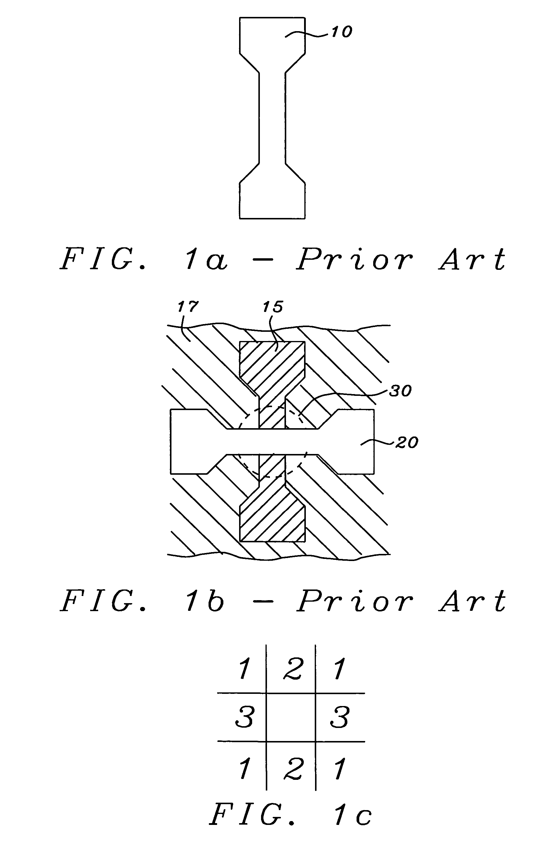
RELATED PATENT APPLICATION [0001] The present application is related to Docket No. HTIRC-03-011, filing date ______, Ser. No. ______, which is assigned to the same assignee as the present application.BACKGROUND OF THE INVENTION [0002] 1. Field of the Invention [0003] This invention relates generally to the fabrication of a giant magnetoresistive (GMR) magnetic field sensor in the current-perpendicular-to-plane (CPP) configuration, more specifically to a method of improving photolithographic masks used in the patterning of such devices. [0004] 2. Description of the Related Art [0005] Magnetic read sensors that utilize the giant magnetoresistive (GMR) effect for their operation must be patterned to produce a required trackwidth. Such patterning is conventionally done using a single photolithographic lift-off mask as both an etching stencil and a deposition mask. The shape of the stencil portion of such a mask permits the necessary trimming of the deposited layers to the required track...

Claims


Application Information

Patent Timeline
IPC IPC(8): G03F7/00
CPCG03F7/094G03F7/405G03F7/36G03F7/203
Inventor CHEN, CHAO-PENGKAJI, RINACHANG, JEI-WEI
Owner HEADWAY TECH INC
Learn More