
Curing light

Active Publication Date: 2006-02-02
DEN MAT HLDG
View PDF94 Cites 41 Cited by
  • Summary
  • Abstract
  • Description
  • Claims
  • Application Information

AI Technical Summary

Benefits of technology

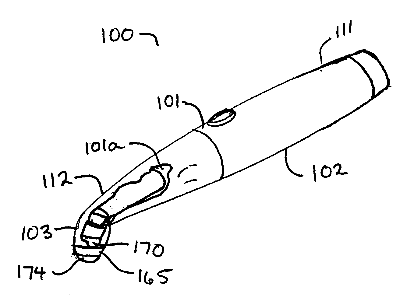
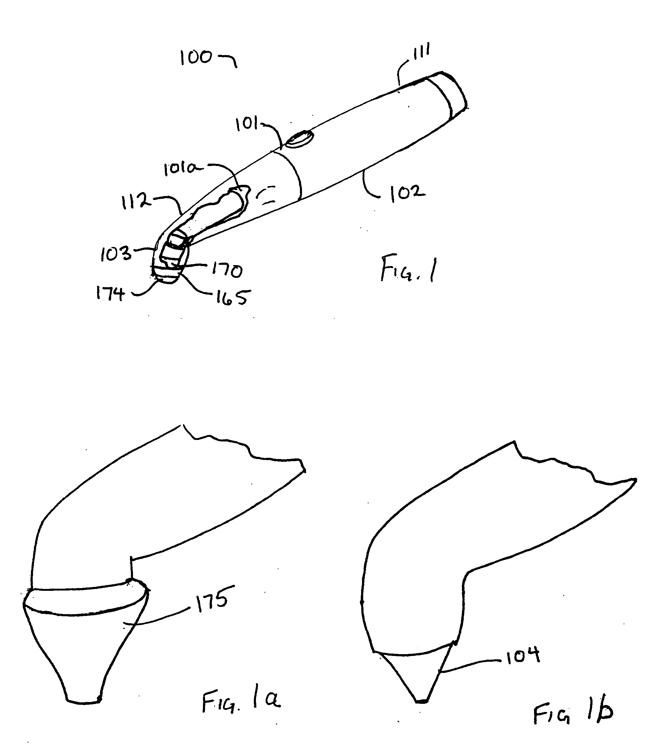
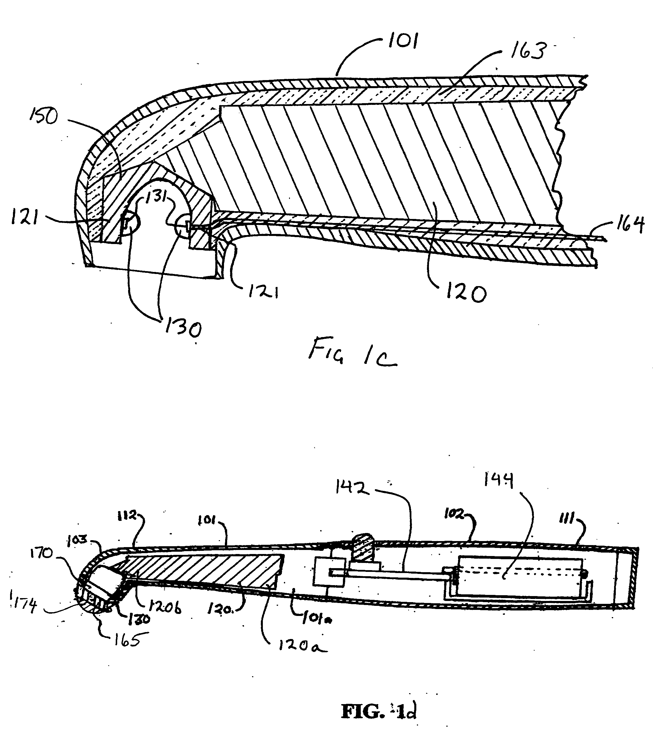
[0011] This invention relates to a dental curing light suitable for curing light curable dental composite materials. The curing light device has a light module housing having a distal end, a proximal end, a handle and a head and neck portion at the proximal end of the housing. The light module housing is of a substantially cylindrical shape having a substantially hollow interior with at least one heat sink located therein. The heat sink has at least two surfaces or mounting platforms situated at locations of at least about 180° from each other. At least two light sources, each of which may be, for example, a lamp, an arc lamp such as a halogen light source, semiconductor light emitting devices, light-emitting chips such as an LED, a solid state LED, an LED array, a fluorescent bulb, and so on, are located, positioned or mounted on the mounting platforms. The light sources emit at least two different wavelengths. The heat sink may take on various shapes, some of which may facilitate the arrangement of the light sources for a longer runtime device.

Problems solved by technology

This inefficiency in capturing some of the available light output may contribute to excessive heat generation, which may lead to shorter run times for the curing devices.
This, however, not only does not overcome the run time problem mentioned above, but at the same time, may create another problem of having the light source being too close to the patient's mouth, causing discomfort to the patient if the tip of the curing device happens to come in contact with the sensitive tissues of the patient's mouth.
However, this only minimally solves the runtime problem mentioned above.
In addition, multiple light sources used in making a curing light capable of multiple wavelengths may further add to excessive heat generation problems if the light sources generate a wide spectrum of light, leading to more heat that needs to be diverted away from the light sources.
Even with light sources generating just the desired wavelength for composite curing, heat generation is still a problem.
Consequently, elaborate cooling systems are needed to handle heat, possibly creating a large, heavy and expensive curing light.
Also, for devices with multiple wavelengths, if more light intensity is generated for one wavelength as compared to a second wavelength at the same power input, unless separate power supplies are used, or power is diverted away in some fashion, the excessive intensity at one wavelength may also lead to excessive heat at the point of generation.

Method used


Image

  • Curing light
  • Curing light
  • Curing light

Examples


Embodiment Construction

[0063] The detailed description set forth below is intended as a description of the presently preferred device provided in accordance with aspects of the present invention and is not intended to represent the only forms in which the present invention may be practiced or utilized. It is to be understood, however, that the same or equivalent objectives and functions may be accomplished by different embodiments and components that are also intended to be encompassed within the spirit and scope of the invention.

[0064] Unless defined otherwise, all technical and scientific terms used herein have the same meaning as commonly understood to one of ordinary skill in the art to which this invention belongs. Although any methods, devices and materials similar or equivalent to those described herein can be used in the practice or testing of the invention, the preferred methods, devices and materials are now described.

[0065] A curing light device useful for curing or activating light-activated...


PUM


Abstract

The present invention relates to a curing light suitable for curing light curable dental composite materials. The curing light device has a light module housing having at least one heat sink located therein. The heat sink has at least two mounting platforms arranged in different geometric arrangements. More than two light sources may be used, emitting at least two different wavelengths. The curing light includes at least one heat sink having various geometric shapes, which facilitate the arrangement of the light sources in the curing light and minimizing the concentration.

Description

CROSS-REFERENCE TO RELATED APPLICATIONS [0001] This application claims the benefit of U.S. provisional patent application Ser. No. 60 / 585,224, filed Jul. 2, 2004, entitled “Dental Light Devices With Phase Change Heat Sink”; 60 / 658,517, filed Mar. 3, 2005, entitled “Apparatus and Method For Radiation Spectrum Shifting in Dentistry Application”; 60 / 594,297, filed Mar. 25, 2005, entitled “Curing Light Having A Detachable Tip”; 60 / 631,267, filed Nov. 26, 2004, entitled “Curing Light Having A Reflector”; 60 / 594,327, filed on Mar. 30, 2005, entitled, “Curing Light”; and 60 / 664,696, filed Mar. 22, 2005, entitled “Curing Light Having A Detachable Tip”; the contents of all of which are hereby incorporated by reference. [0002] The present application includes claims that may be related to the claims of co-pending United States patent applications, Ser. No. 10 / ______, to be concurrently filed, entitled “Illumination System for Dentistry Applications”; Ser. No. 10 / ______, to be concurrently fil...

Claims


Application Information

Patent Timeline
IPC IPC(8): A61C3/00
CPCA61C19/004Y10S362/804Y10S362/80A61K8/19A61K8/20A61K8/21A61K8/24A61Q11/00A61K6/864A61K6/884C08L91/06A61C19/00
Inventor ROSENBLOOD, KENNETHQUAN, NANCY N.ROSE, ERIC P.
Owner DEN MAT HLDG
Learn More