Inorganic carbon removal

a technology of inorganic carbon and removal, applied in the field of inorganic carbon removal, can solve the problems of adverse effects on the accuracy of tc and ic measurements, and it is impossible to precisely determine the concentration of toc from the small difference between the large tc and ic concentration, so as to minimize the removal or loss of volatile organic compounds

Inactive Publication Date: 2006-02-02
PETROPAVLOVSKIKH VIATCHESLAV A +1
View PDF3 Cites 6 Cited by
  • Summary
  • Abstract
  • Description
  • Claims
  • Application Information

AI Technical Summary

Benefits of technology

[0014] Accordingly, a general object of the present invention is to provide improved methods and related apparatus for processing a sample fluid for the selective removal of inorganic carbon, as defined herein, while minimizing the removal or loss of volatile organic compounds.

Problems solved by technology

However, when the concentration of TOC is significantly less than the IC concentration, it is essentially impossible to precisely determine the TOC concentration from the small difference between the large TC and IC concentrations.
The precision of the TC and IC measurements is adversely affected by the normal “noise” associated with any analytical measurement and such effect may be substantial in relation to a relatively small, but still significant, TOC content.

Method used


Image

  • Inorganic carbon removal
  • Inorganic carbon removal
  • Inorganic carbon removal

Examples


example 1

[0059] The following tests were performed to demonstrate the practice and efficiency of this invention in the removal of a volatile electrolyte, such as carbon dioxide, from an aqueous sample at varying temperatures.

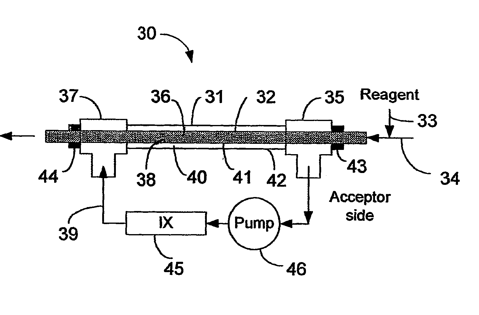
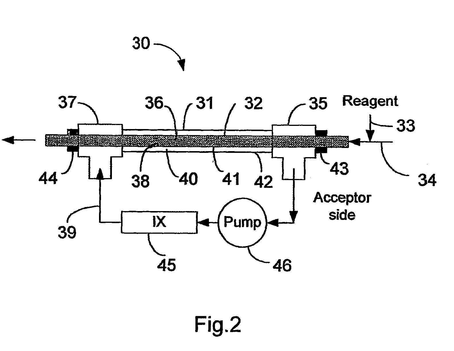
[0060] A tubular design gas transfer module similar to that illustrated in FIG. 2 was used in this example. Carbon dioxide, at a concentration of 28 ppm C in water, was passed through the inside of a tubular Teflon AF membrane. The temperature was changed by heating the acceptor stream, which was deionized water.

[0061] The results are illustrated in FIG. 4 which plots IC removal efficiency against residence time of the sample in the IC transfer unit at three temperatures, 30° C., 50° C. and 70° C. FIG. 4 shows that, at each temperature, essentially 100% removal of IC from the sample fluid was achieved in under three minutes (less than 180 seconds).

example 2

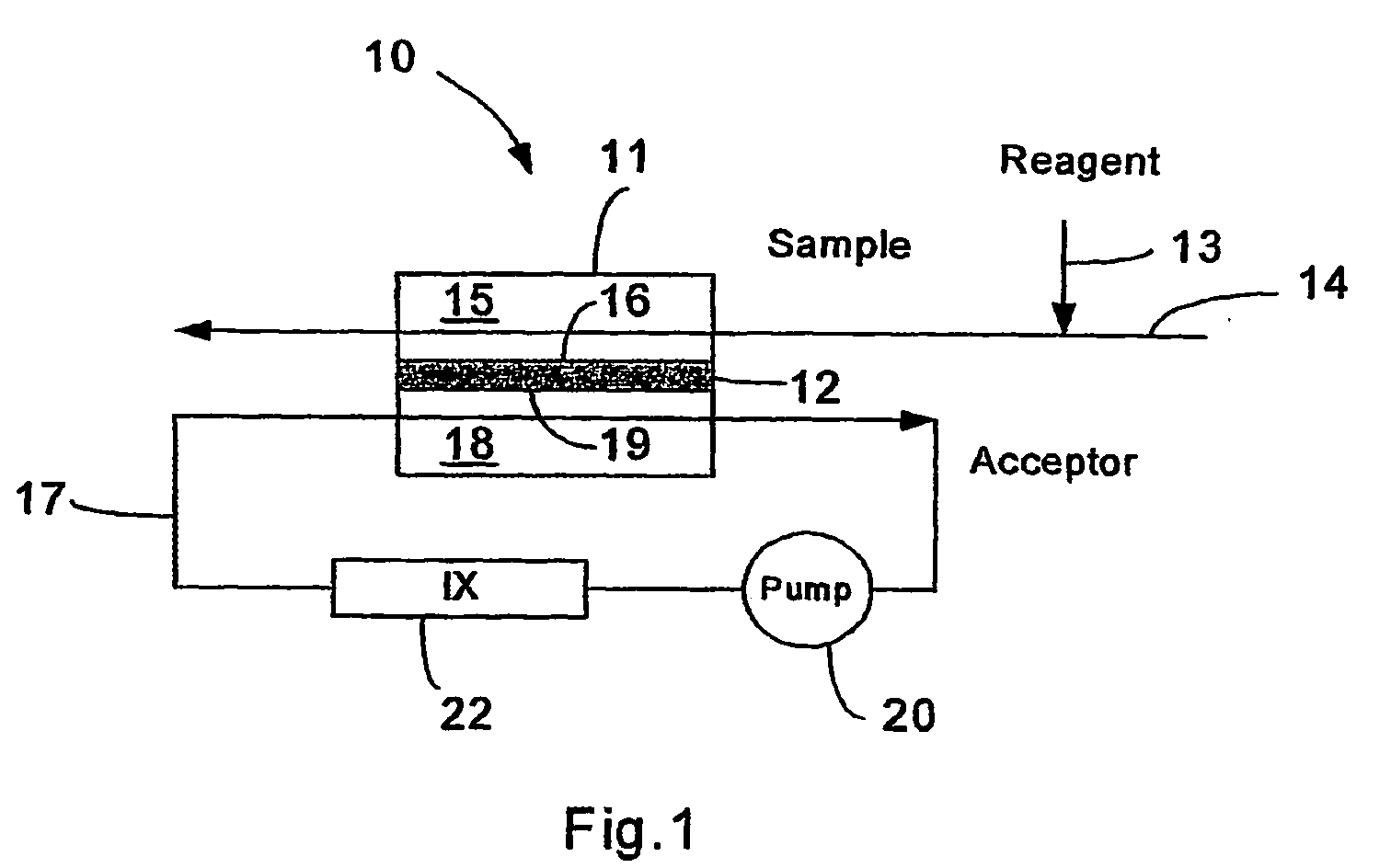
[0062] Another set of experiments was performed using an IC transfer module containing a flat or planar PFA membrane similar to the membrane configuration illustrated in FIG. 1. For this set of experiments, the sample residence time in the IC transfer module was changed by varying the sample flow rate. The results are shown in FIG. 5 which plots IC removal efficiency against residence time of the sample in the IC transfer unit at three concentrations of C and IC in the sample, 5 ppm C, 25 ppm C and 50 ppm C. FIG. 5 shows that removal efficiency for any given residence time does not vary significantly with IC concentration over a broad range.

example 3

[0063] In general, a solution containing a volatile organic compound will lose a very small amount of this compound while going through the IC module of the present invention. However, the amount that is lost in this way can be minimized through the choice of the membrane material and by minimizing the sample residence time.

[0064] In this example, two different membranes were tested for IC removal in accordance with the present invention. The concentration of various volatile organic compounds in an aqueous sample stream was determined before and after the sample was passed through each of two IC transfer units according to the present invention, one such unit utilizing a Teflon AF membrane, the other utilizing a Gortex membrane. In addition, the sample stream was tested for IC (as CO2) concentration both before and after passing through each of the two IC transfer units. A relatively short residence time of 15 seconds in the IC transfer units was used for these tests.

[0065] The r...


PUM

PropertyMeasurementUnit
temperatureaaaaaaaaaa

Abstract

Methods and related apparatus are disclosed for selective removal of inorganic carbon from a fluid sample using selective membranes to minimize the loss of volatile organic compounds from the fluid sample prior to analysis for determination of the total organic carbon contents of the sample.

Description

FIELD OF THE INVENTION [0001] This invention relates particularly to methods and apparatus for facilitating the selective and sensitive detection of organic carbon compounds in water by first treating an aqueous solution for the selective removal of inorganic carbon (IC), which may be in the form of CO2, HCO3—, and / or CO3−2, using a gas-permeable membrane having a relatively high permeability to carbon dioxide and a relatively low permeability to volatile organic compounds. More generally, the methods of this invention can be applied to separating IC from a fluid stream, which can be a gas or liquid stream, without substantially removing or affecting volatile organic components of that gas or liquid stream. BACKGROUND OF THE INVENTION [0002] In recent years it has become increasingly important to be able to accurately and reproducibly determine to very low levels, on the order of a few parts per billion, the organic carbon content of an aqueous sample. Sensitive industrial applicati...

Claims


Application Information

Patent Timeline
Patent Type & Authority Applications(United States)
IPC IPC(8): B01L11/00B01L99/00B01D53/22B01D61/24B01D61/36B01D71/32B01D71/36C02FG01N1/28G01N1/34G01N1/40G01N31/00G01N33/00G01N33/18
CPCB01D53/22Y10T436/255B01D61/246B01D61/36B01D71/32B01D71/36B01D2257/504B01D2311/04B01D2311/06B01D2325/02B01D2325/20B01J41/04G01N1/4005G01N33/1846G01N2001/4016Y02C10/10B01D53/228B01D2311/12B01D2311/18B01D2311/2623Y02C20/40
Inventor PETROPAVLOVSKIKH, VIATCHESLAV A.GODEC, RICHARD D.
Owner PETROPAVLOVSKIKH VIATCHESLAV A
Why Eureka
Try Eureka