Gas shut-off valve assembly

a technology of shut-off valve and assembly, which is applied in the direction of functional valve types, vessel construction details, gas/liquid distribution and storage, etc., can solve the problems of releasing hydrogen, and achieve the effect of easy determination

Inactive Publication Date: 2006-02-09
TOMLINSON JEREMY JOHN +2
View PDF0 Cites 12 Cited by
  • Summary
  • Abstract
  • Description
  • Claims
  • Application Information

AI Technical Summary

Benefits of technology

[0024] The valve assembly can further comprise a knob that is attached to the shut-off valve and that can be manipulated to rotate the shut-off valve. The knob can be marked to indicate when the shut-off valve is in an opened or closed position, thereby ensuring that an operator

Problems solved by technology

Conversely, cooling the alloy will cause it to absorb hy

Method used


Image

  • Gas shut-off valve assembly
  • Gas shut-off valve assembly
  • Gas shut-off valve assembly

Examples


first embodiment

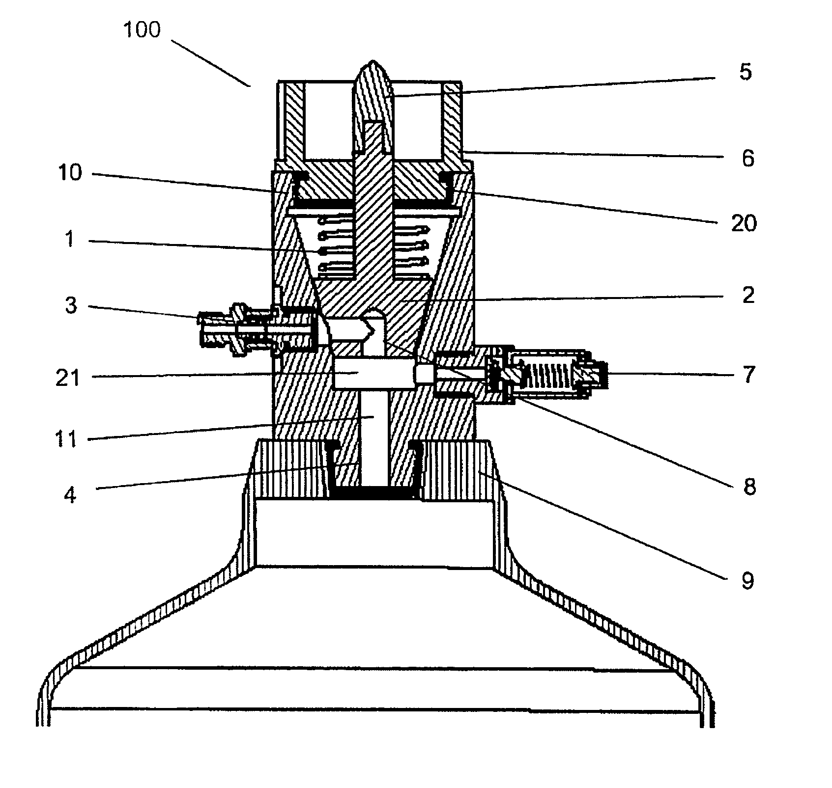
[0042] According to the invention and referring to FIGS. 3 to 6, a valve assembly 100 is provided that comprises four major components, namely: a rotatable gas shut-off valve 2, a quick-connect / detach outlet connector 3, a safety pressure relief device 7, and a bottle / canister inlet connector 4.

[0043] Directional terms such as “top”, “bottom”, and “side” used in reference to the assembly 100 are based on the inlet connector 4 being hereby defined as being at the “bottom” of the assembly 100. However, it is to be understood that such directional terms are used merely for convenient reference to assist in the description of the assembly 100, and are not to be construed as limiting the orientation of the assembly 100 in use or in connection to any other structure.

[0044] The shut-off valve 2 has a frusta-conical shape and is seated with its narrow end facing the bottom of a matching frusta-conical cavity and towards the inlet connector 4, i.e. upstream of the gas flow. Alternatively, t...

second embodiment

[0059] the assembly 102 is particularly usefully as it enables a gas-tight seal even if the spring 1 fails, as gas pressure from the bottle 9 will bias the valve 2 against the cavity surface.

[0060] Referring now to FIGS. 8(a) to (c) and according to a third embodiment of the invention, a valve assembly 104 is provided which is similar to the first embodiment except that the valve 30 a generally spherical shape, and the cavity extends laterally across the body 10 and has a generally hemispherical end that matches the shape of the valve 30. Also, the outlet connector 3 extends outwardly from the top of the body 10, and the knob 5 extends outwardly from the side of the valve 30 and through the knob guard 6, which is on or mounted to the side of the body 10 and serves to close the cavity. A compression spring 31 is located between the knob guard 6 and the valve 30 to bias the valve 30 against the cavity and establish a gas-tight seal therebetween.

[0061] A pair of blind openings 22 are ...


PUM


Abstract

This invention relates to a valve assembly for metal hydride hydrogen storage (MHHS) or chemical hydride hydrogen storage (CHHS) devices. The valve assembly comprises a body with an inlet connector for connecting to the MHHS or CHHS device, an outlet connector for connecting to an external device, a cavity in the body that is in gas communication with the inlet and outlet connectors, and a shut-off valve in the cavity that can be moved between an opened position that permits gas flow between the inlet and outlet connectors, and a closed position that denies said gas flow. The outlet connector has a first valve therein that is biased to remain closed when external pressure thereon is less than or equal to ambient pressure, thereby impeding at least atmospheric gas backflow into the cavity. The outlet connector can also have a second, one-way valve that permits gas flow out of the valve assembly only, as well as a bypass mechanism including a gas passage coupled to the cavity and upstream of the first and second valves, through which gas can be transmitted to the canister during charging.

Description

FIELD OF THE INVENTION [0001] This invention relates generally to a gas shut-off valve assembly, and in particular, to a shut-off valve assembly for a gaseous pressure vessel, such as a metal hydride hydrogen storage (MHHS) or a chemical hydride hydrogen storage (CHHS) canister. BACKGROUND OF THE INVENTION Hydrogen Storage [0002] Today, a major obstacle to the wide use of highly efficient and zero-emission fuel cells, especially for portable applications, is the lack of a safe, convenient and economical hydrogen storage device and supply system. [0003] Hydrogen is naturally a gas at ambient temperatures. There are generally three ways in which hydrogen is stored: compressed gas, liquefaction, and solid storage by absorption into another substance. The primary conventional technologies for storing hydrogen are compressed and liquid hydrogen storage tanks. Compressing hydrogen gas is the most common storage method. However, very high storage pressures are necessary to store practical...

Claims


Application Information

Patent Timeline
IPC IPC(8): F17D1/00
CPCF16K5/0214F16K5/185F17C13/04Y02E60/321F17C2205/0329F17C2205/0332F17C2270/0745F17C2205/0394F17C2221/012F17C2223/0123F17C2223/036F17C2260/011F17C2205/0385Y02E60/32Y10T137/87861
Inventor TOMLINSON, JEREMY JOHNSHEN, JOHN JIANYUEDONG, ZUOMIN
Owner TOMLINSON JEREMY JOHN
Why Eureka
Try Eureka