Totally hermetically sealed motor for a vehicle

a technology of hermetically sealed motors and vehicles, applied in the direction of mechanical energy handling, magnetic circuit rotating parts, shape/form/construction, etc., can solve the problems of lowering installation performance and/or cooling effect, labor saving in maintenance, affecting mass-production characteristics, etc., to save maintenance and inspection time, reduce the number of manufacturing steps, and improve the effect of cooling performan

Inactive Publication Date: 2006-02-09
KK TOSHIBA
View PDF10 Cites 17 Cited by
  • Summary
  • Abstract
  • Description
  • Claims
  • Application Information

AI Technical Summary

Benefits of technology

[0024] Accordingly, one object of the present invention is to provide a novel totally hermetically sealed motor for a vehicle that is suitable for mass production and wherein the number of manufacturing steps can be reduced, saving of maintenance and inspection time can be achieved, and wherein cooling performance is improved.

Problems solved by technology

However, it is difficult for a filter to capture all the dust, so dust penetrating into the motor gradually adheres and accumulates in the interior of the motor, causing a lowering of installation performance and / or cooling effect.
The interval at which periodic disassembly of the motor must be performed can thereby be extended, resulting in laborsaving in regard to maintenance.
However, with a motor for vehicle drive of this totally hermetically sealed construction, there are the following three problems.
The first problem is that, since the cooling fins 15, constituting the coolers c, made of thin sheet such as for example aluminum material, must be joined by welding to the outer peripheral surface of the pipes 14, this large number of cooling fins 15 must be welded on one at a time: this adversely affects mass-production characteristics and involves a large number of manufacturing steps, resulting in increased costs.
The second problem is that a large number of ventilation passages 14a of the pipes 14 are arranged in a condition crowded together in the pipe structure and in addition the structure is partitioned by a large number of cooling fins 15, so dust or scraps of paper or fluff present in the atmosphere tend to adhere thereto, adversely affecting the cooling performance as dust gradually causes blockages between the pipes 14 with lapse of time of use.
However, owing to the presence of the intersecting cooling fins 15, it is difficult to thoroughly remove dust etc that has become attached in cavities.
In other words, thermal conduction is poor.
Consequently, the coolers c cannot be said to be effective.

Method used


Image

  • Totally hermetically sealed motor for a vehicle
  • Totally hermetically sealed motor for a vehicle
  • Totally hermetically sealed motor for a vehicle

Examples


first embodiment

[0054] A totally hermetically sealed motor according to a first embodiment of the present invention is described with reference to FIG. 4, FIG. 5 and FIG. 6.

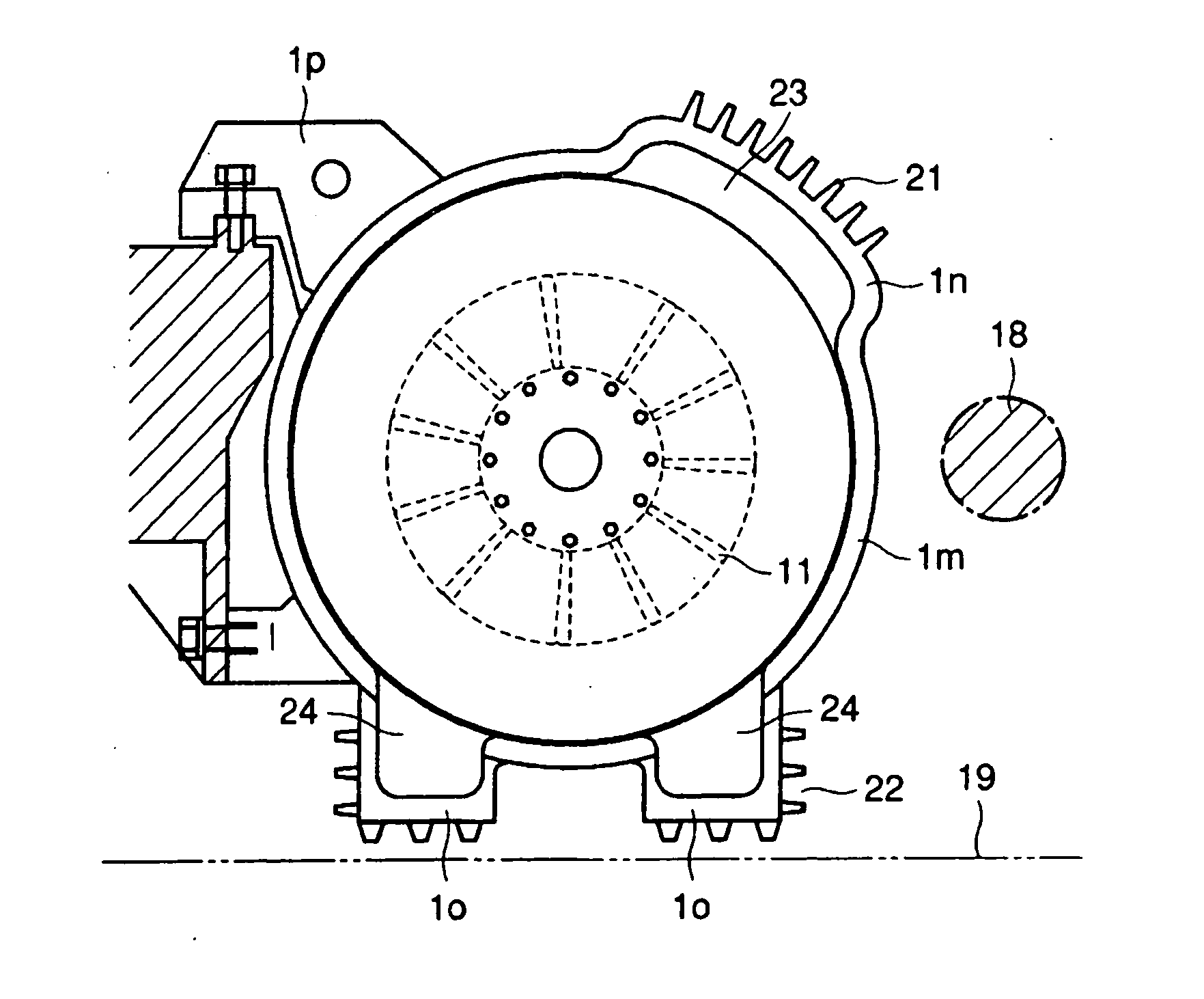
[0055] As shown in FIG. 6, the stator frame 1 comprises: a housing 1m whereof a modified tubular body that is mounted on the outer peripheral surface of the stator core 2 is virtually recessed in two locations in the direction of the rotary axis of the rotor; a cooling section in that is integrally formed at one of the recesses of this housing 1m, that is formed with a passage 23 for the airflow generated by the circulating fan 11 by formation of a prescribed gap with respect to the outer peripheral surface of the stator core 2 and that is of increased heat-radiating area compared with the housing 1m; two feet 1o of increased heat-radiating area compared with the housing 1m that are placed on the installation surface and that form passages 24 for the airflow generated by the circulating fan 11 by formation of a prescribed gap w...

second embodiment

[0078] Next, the construction of a totally hermetically sealed motor for vehicle drive according to a second embodiment of the present invention is described with reference to FIG. 8 and FIG. 9.

[0079] In this embodiment, a plurality of heat-absorbing fins 25 are formed along the axial direction of the rotor in positions on the opposite side to the heat-radiating fins 21 within the airflow passage 23 in the interior of the cooling section 1n of the stator frame 1, seen from the axial direction of the motor. Other details are the same as in the case of the first embodiment.

[0080] In this case, since the plurality of heat-absorbing fins 25 extend in the axial direction in opposing positions (i.e. positions opposite the heat-radiating fins 21 on the opposite side thereto about the housing 1m as center) cooling performance is improved, due to conduction of heat to the heat-radiating fins 21 by the shortest distance. Further improvement in the cooling performance of the motor can be ach...

third embodiment

[0081] Next, a totally hermetically sealed motor for vehicle drive according to a third embodiment of the present invention is described with reference to FIG. 10 and FIG. 11. In this embodiment, a plurality of heat-absorbing fins 25 are formed along the axial direction of the rotor in a position opposite the heat-radiating fins 21 within the airflow passage 23 in the interior of the cooling section in of the stator frame 1, seen from the axial direction of the motor and, in addition, a plurality of heat-absorbing fins 26 are formed along the axial direction of the rotor in a position opposite the respective heat-radiating fins 22 within the airflow passage 24 in the interior of the two feet 1o of the stator frame 1, seen from the axial direction of the motor. Other details are the same as in the case of the first embodiment.

[0082] In this case, since the plurality of heat-absorbing fins 26 extend in the axial direction of the rotor in the same way as the heat-radiating fins 22, co...


PUM


Abstract

A stator frame (1) comprises: a housing (1m) whereof a modified tubular body mounted on the outer peripheral surface of a stator core (2) and that is virtually recessed at two locations in the direction of the rotary axis of a rotor; a cooling section (1n) that is integrally formed with one recess of this housing (1m) and wherein a passage (23) for the airflow generated by a circulating fan (11) is formed by forming a prescribed gap with respect to the outer peripheral surface of the stator core (2) and comprising heat-radiating fins (21); a foot (1o) that is integrally formed with another recess of this housing (1m) and wherein a passage (24) for the airflow generated by the circulating fan (11) is formed by forming a prescribed gap with respect to the outer peripheral surface of the stator core (2) and comprising heat-radiating fins (22); and a mounting section (1p).

Description

CROSS-REFERENCE TO RELATED APPLICATION [0001] This application claims benefit of priority to Japanese application No. JP 2004-223968 filed 30th Jul., 2004, the entire contents of which are incorporated by reference herein. BACKGROUND OF THE INVENTION [0002] 1. Field of the Invention [0003] The present invention relates to a totally hermetically sealed motor for a vehicle that drives for example a railway vehicle, having a totally hermetically sealed construction whereby the atmosphere is not admitted to the interior of the motor. [0004] 2. Description of the Related Art [0005] In a railway vehicle such as a train, a motor for vehicle drive is mounted on a chassis that is arranged below the vehicle body and the vehicle is driven by transmitting the torque (turning force or turning effort) of this motor to the wheels through a gear mechanism. [0006] Conventionally, motors of this type are of the open, self-ventilating cooling type, in which cooling is performed by passing external air...

Claims


Application Information

Patent Timeline
Patent Type & Authority Applications(United States)
IPC IPC(8): H02K9/00H02K3/24H02K5/00
CPCH02K5/10H02K7/006H02K5/18
Inventor NODA, SHINICHIKOBAYASHI, YOSHITAKAOKADA, KOJI
Owner KK TOSHIBA
Why Eureka
Try Eureka