
Rotary atomizer, and air bearing protection system for rotary atomizer

a technology of air bearing protection and rotary atomizer, which is applied in the direction of bearings, shafts and bearings, bearings, etc., can solve the problems of difficulty in maintenance, large heat and load caused by continuous operation, and complex system structure, so as to reduce manufacturing cost, simplify system structure, and save maintenance and repair cost

Inactive Publication Date: 2008-03-18
KIM JUNG WON
View PDF5 Cites 15 Cited by
  • Summary
  • Abstract
  • Description
  • Claims
  • Application Information

AI Technical Summary

Benefits of technology

[0007]Accordingly, the present invention has been made in order to solve the above problems occurring in the prior art, and it is an object of the invention to provide a rotary atomizer and an air bearing protection system for the rotary atomizer, in which the structure is simplified to reduce the manufacturing cost, an air bearing is used to enable high-speed rotation along with savings in the maintenance and repair, and compressed air can be temporarily supplied at emergency such as interruption of the compressed air, thereby improving the stability and durability of the entire system such as prevention of air bearing failure.
[0010]According to the present invention, the structure of the system can be simplified to reduce the manufacturing cost, an air bearing is used to enable high-speed rotation along with savings in the maintenance and repair cost, and compressed air can be temporarily supplied at emergency such as interruption of the compressed air, thereby improving the stability and durability of the entire system such as prevention of air bearing failure.

Problems solved by technology

In this approach, an accelerator is used for enabling high-speed rotation and thus a lot of heat and load are caused upon the continuous operation.
In order to remove this heat, lubricating equipment is used, which leads to complexity in the system structure, consequently to difficulties in the maintenance and an increase in the manufacturing cost.

Method used


Image

  • Rotary atomizer, and air bearing protection system for rotary atomizer
  • Rotary atomizer, and air bearing protection system for rotary atomizer

Examples


Embodiment Construction

[0013]Reference will now be made in detail to the preferred embodiments of the present invention, examples of which are illustrated in the accompanying drawings.

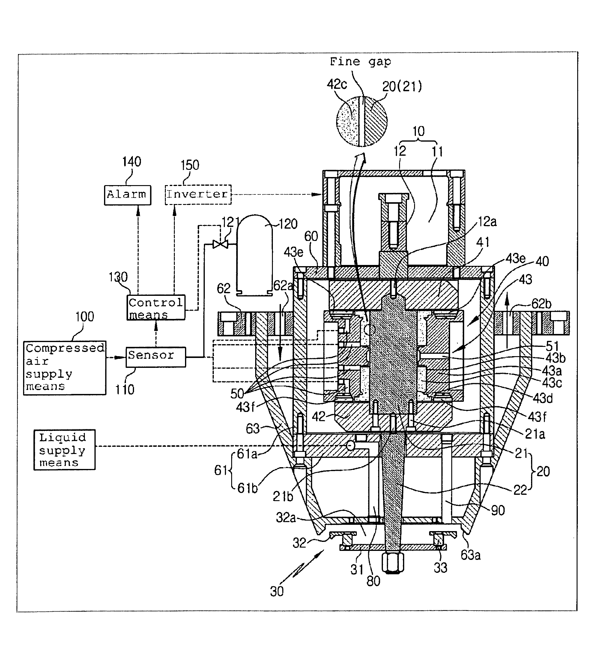
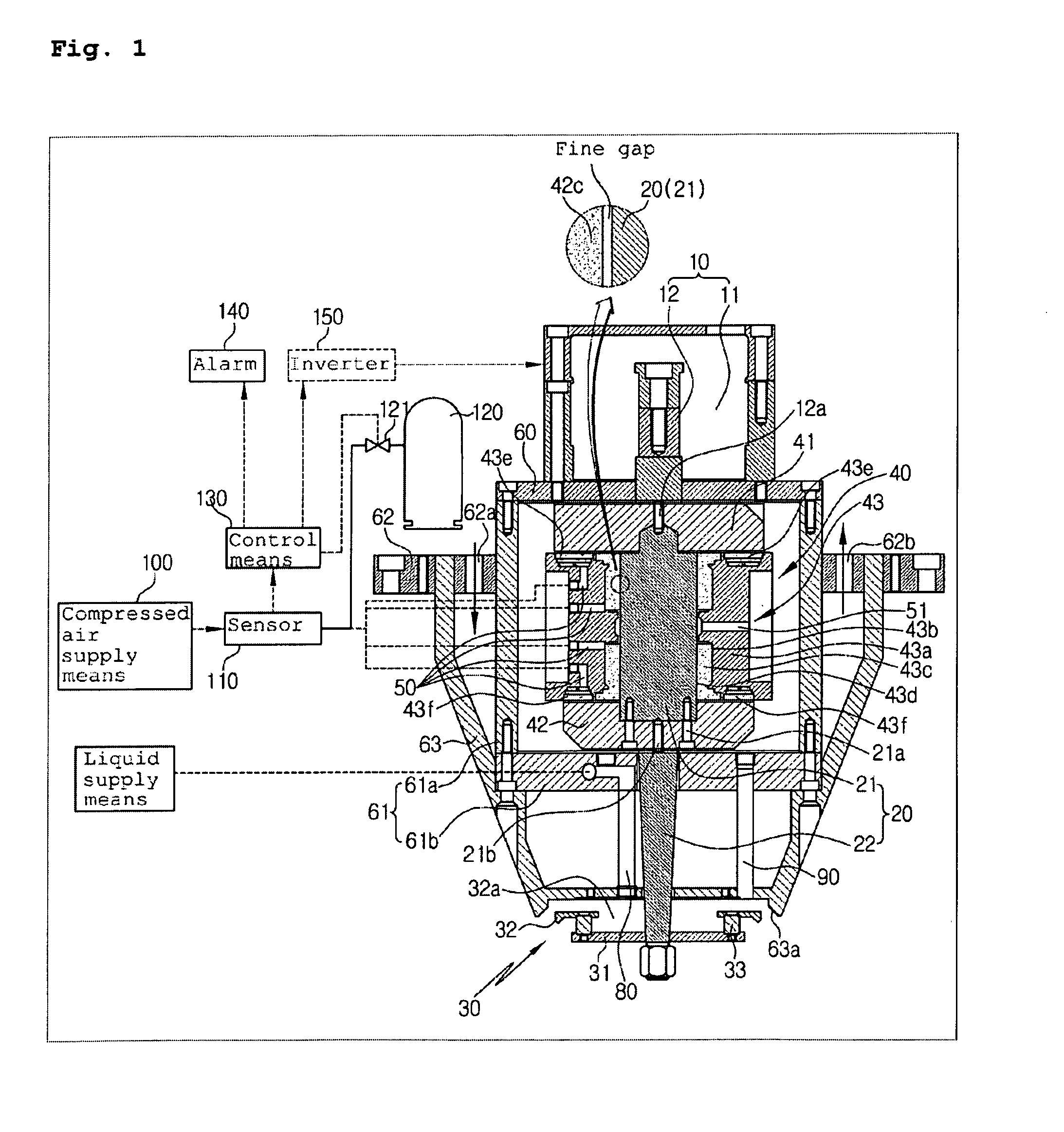
[0014]FIG. 1 is a sectional view showing a rotary atomizer and an air-bearing protection system according to an embodiment of the invention.

[0015]The rotary atomizer according to an embodiment of the invention includes a drive motor 10 having a stator 11 and a rotor 12, and a rotation shaft 20 being rotated by means of rotating force of the rotor 12. The rotation shaft 20 has a desired length and installed in vertical direction. A spray means 30 is disposed at the lower end portion of the rotation shaft 20 and sprays externally-supplied liquid into a state of fine particles. A shaft support means 40 is connected to the upper end of the rotation shaft 20 so as to transmit power of the rotor 12 and also rotatably support the rotation shaft 20.

[0016]According to an embodiment of the invention, the shaft support means 40 include...


PUM


Abstract

Disclosed herein are a rotary atomizer and an air bearing protection system for the rotary atomizer. The structure of the system is simplified to reduce the manufacturing cost. An air bearing is used to enable high-speed rotation along with savings in the maintenance and repair cost. Compressed air can be temporarily supplied at emergency such as interruption of the compressed air. Thus the stability and durability of the entire system are improved, such as prevention of air bearing failure.

Description

BACKGROUND OF THE INVENTION[0001]1. Field of the Invention[0002]The present invention relates to a rotary atomizer and an air bearing protection system for the rotary atomizer, and more particularly to, a rotary atomizer and an air bearing protection system for the rotary atomizer, in which the structure is simplified to reduce the manufacturing cost, an air bearing is used to enable high-speed rotation along with savings in the maintenance and repair cost, and compressed air can be temporarily supplied at emergency such as interruption of the compressed air, thereby improving the stability and durability of the entire system such as prevention of air bearing failure.[0003]2. Background of the Related Art[0004]A rotary atomizer refers to a fine liquid-drop spray system. For example, it can be adopted in a semi-dried reactor for removing toxic acidic gas in an incineration process. Here, the rotary atomizer sprays Ca(OH)2, which causes desulphurization reaction, in the form of fine l...

Claims


Application Information

Patent Timeline
IPC IPC(8): B05B3/10B05B1/28F16C32/00F16C32/06F16C17/10B05B15/00B05B3/00
CPCB05B3/1035F16C17/10F16C17/20F16C32/064B05B3/001
Inventor KIM, JUNG WON
Owner KIM JUNG WON
Learn More