Dispenser cathode

a dispenser cathode and dispenser technology, applied in the direction of thermionic cathodes, discharge tubes/cathodes, electron beam apparatus, etc., can solve the problems of limiting the lifetime and emission of these conventional dispenser cathodes, severe inhomogenity, and the emission current is too high for the electron beam apparatus, so as to achieve the breakage of the energy distribution function of the electron beam

Inactive Publication Date: 2006-02-09
ASML NETHERLANDS BV
View PDF9 Cites 10 Cited by
  • Summary
  • Abstract
  • Description
  • Claims
  • Application Information

AI Technical Summary

Benefits of technology

[0026] In another embodiment of the dispenser cathode of the present invention, the emission surface has at least one convex surface. This helps producing a diverging beam. In a further embodiment, the emission surface is convex at the location of an emission area. When the dispenser cathode is used in high-resolution electron beam systems, it is preferred to use a diverging electron beam, in order to avoid cross-overs in the electron beam, which causes a broadening of the ene...

Problems solved by technology

This limits the lifetime and emission of these conventional dispenser cathodes.
However, the holes in the emission surface also induce a severe inhomogenity in the radiation from the cathode.
Thus, the emission current is too high for the electron beam apparatus.
Furthermore, since more electrons are emitted in the same period ...

Method used


Image

  • Dispenser cathode
  • Dispenser cathode
  • Dispenser cathode

Examples


Embodiment Construction

[0058] In the figures, entities with the same reference numbers relate to the same or corresponding features.

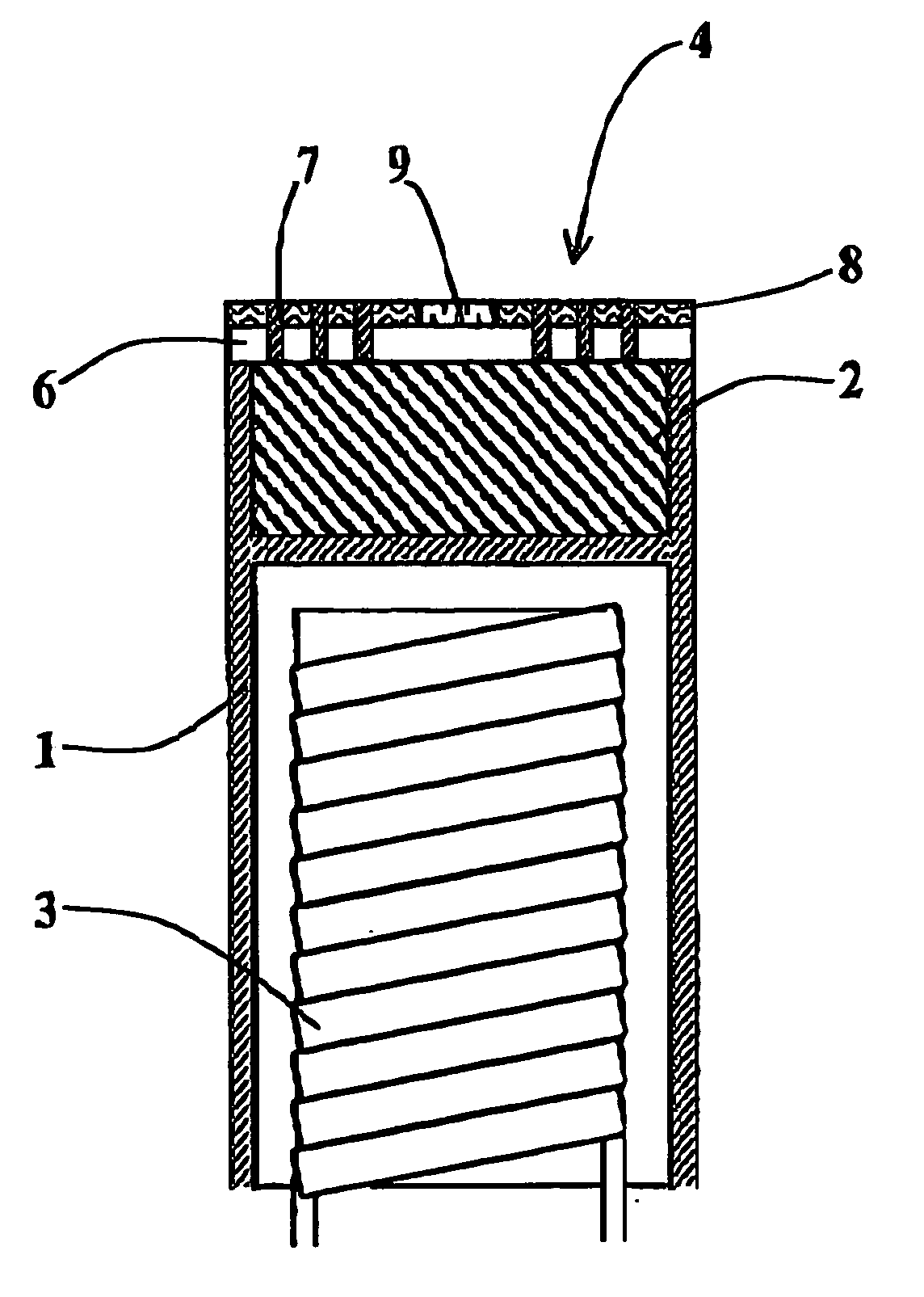
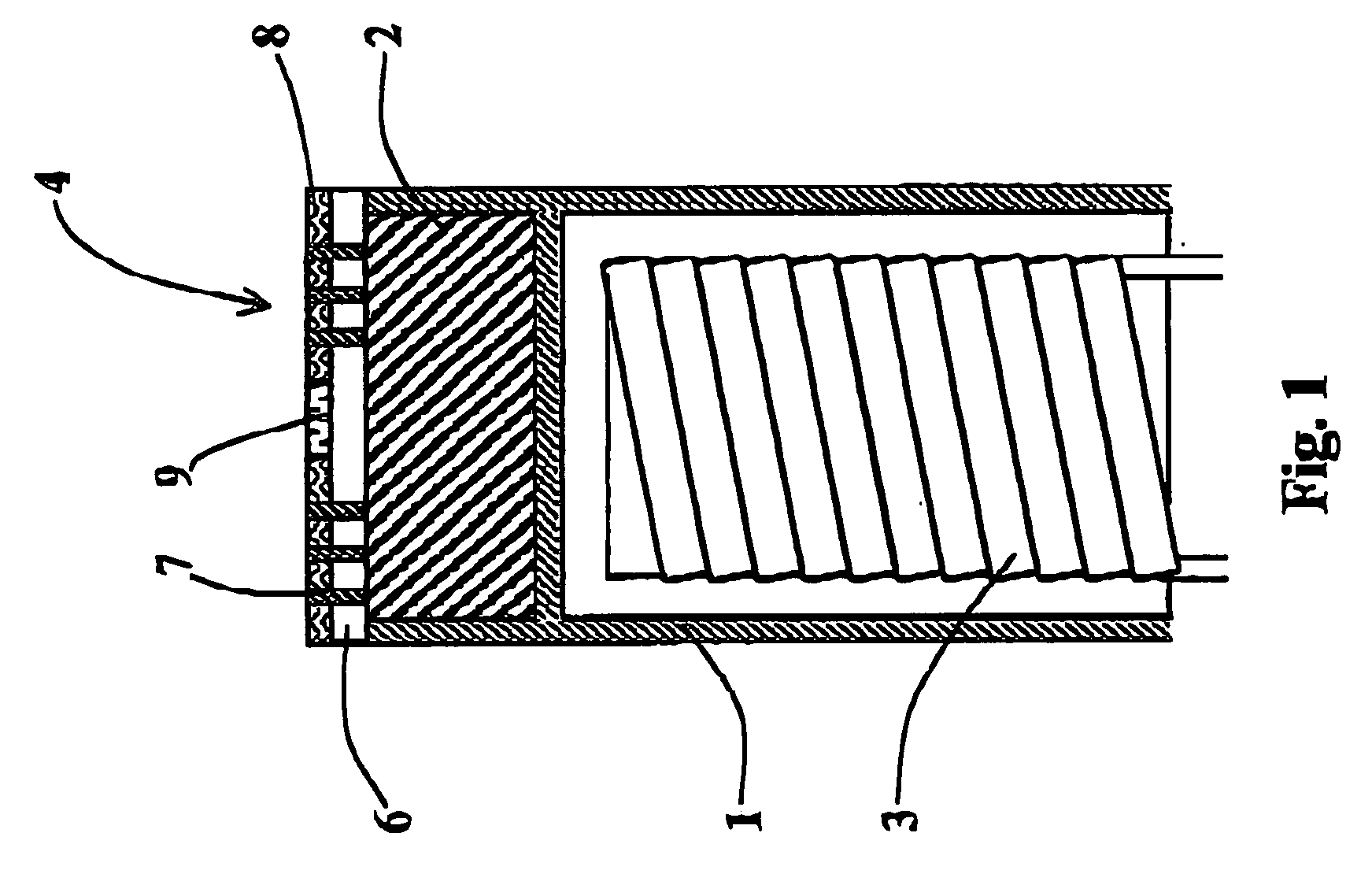
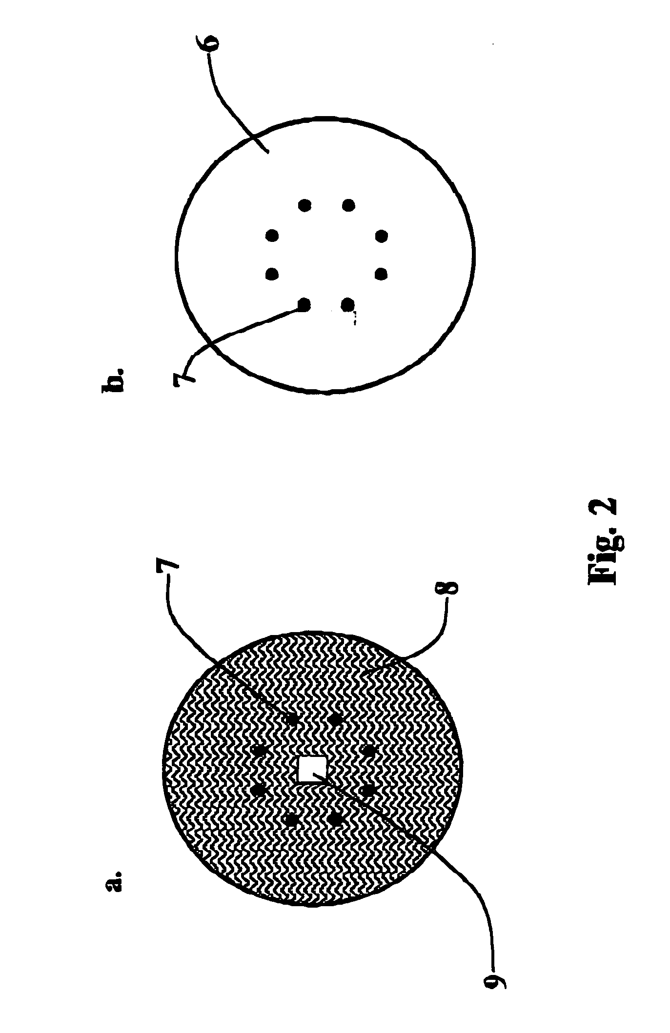
[0059]FIG. 1 shows a first embodiment of a dispenser cathode of the present invention. The dispenser cathode has a cathode body 1, the upper part of which forming a reservoir filled with compounds 2 that dispense, when heated by a heating element 3, at least one kind of work-function-lowering particles towards the emission side surface 4 of the reservoir 2. The emission side surface 4 of the reservoir 1 is divided into two types of areas as shown in FIGS. 2a and 2b, showing a top view of the dispenser cathode of FIG. 1.

[0060] The first type of area of the emission side surface 4 is the emission area 9 which is responsible for the emission of electrons. The emission area is usually coated with work function lowering material, like iridium, osmium or other platinum-group metals, or scandate. These materials or compositions are known to a man skilled in the art.

[0061] The sec...


PUM


Abstract

A dispenser cathode which comprises an emission surface, a reservoir for material releasing, when heated, work-function-lowering particles, and at least one passage for allowing diffusion of work-function-lowering particles from said reservoir to said emission surface, said emission surface comprising at least one emission area and at least one non-emission area covered with emission-suppressing material and surrounding each emission area, said non-emission area comprising at least one passage connecting said reservoir with said non-emission area and debouching within a diffusion length distance from an emission area for allowing diffusion of work-function-lowering particles from said reservoir to said emission area.

Description

FIELD OF THE INVENTION [0001] The present invention relates to thermionic cathodes, in particular for use in a lithography system, in particular a multi-beam lithography system. PRIOR ART [0002] Thermionic cathodes, more specific controlled porosity dispenser-type thermionic cathodes, are well known in the art. These dispenser cathodes are commonly used in for instance televisions, computer monitors and microwave ovens. Such a dispenser cathode usually comprises a cathode body with a reservoir comprising a cavity filled with work-function-lowering material and with an emission surface, and a heating element for generating the heat needed to cause work function lowering particles to diffuse from the reservoir to an emission area on the emission surface and to create the thermionic emission. In general, the entire emission surface is used as emission area. [0003] There are several types of reservoirs known in the art. In a first type of reservoir, the cavity is filled with a porous ma...

Claims


Application Information

Patent Timeline
IPC IPC(8): H01J1/28
CPCH01J1/28H01J37/065H01J2237/3175B82Y40/00H01J2237/31754H01J2237/31774B82Y10/00H01J37/3177H01J29/04
Inventor STEENBRINK, STIJN WILLEM HERMAN KARELKRUIT, PIETER
Owner ASML NETHERLANDS BV
Why Eureka
Try Eureka