Drive mechanism

a technology of drive mechanism and drive unit, which is applied in the direction of mechanical vibration separation, transducer diaphragm, instruments, etc., can solve the problems of generating significant stress, preventing the realization of miniaturization and weight saving of portable terminal devices, and no conventional example of employing oscillation of magnetic body as driving sour

Inactive Publication Date: 2006-02-09
SEIKO EPSON CORP
View PDF16 Cites 38 Cited by
  • Summary
  • Abstract
  • Description
  • Claims
  • Application Information

AI Technical Summary

Problems solved by technology

There seems to be no conventional example of employing oscillation of the magnetic body as the driving source.
Nevertheless, since a speaker and vibrating motor are respectively mounted in the foregoing portable terminal apparatus, mounting procedures for the respective items are necessary, and this hindered the realization of miniaturization and weight saving of the portable terminal apparatus.
Further, as described above, when a vibrating motor is used, since the structure employed a disproportionate weight balancer, significant stress was generated in the rotational axis and bearing, and, as a result, there is a problem in that the life duration of the vibrating motor will shorten.
Further, when the diaphragm contains a magnetic coil, the conductive material oscillates in addition to the diaphragm, and the oscillation within the diaphragm will vary, and conversions corresponding to low frequencies will also become difficult.
And, since a certain amount of space is required between the permanent magnet and the coil in order to enable the oscillation of the diaphragm, there is an additional problem in that the magnetic efficiency will deteriorate.
Nevertheless, in this state, since electricity is not provided to the electromagnet, there is a problem in that the behavior of the micro mirror will be unstable.
Further, there is an additional problem in that the displacement of the micro mirror cannot be controlled in an analog manner.
However, with this type of electric motor, there is a structural limitation in the high output of rotating torque even upon increasing the number of phases or increasing the value of the excitation current, and development of improved technology is desirable.

Method used


Image

  • Drive mechanism
  • Drive mechanism
  • Drive mechanism

Examples


embodiment 1

[0079] Next, Embodiment 1 of the present invention is described with reference to the drawings. Incidentally, the first magnetic material corresponds to a coil, and the second magnetic material corresponds to a permanent magnet.

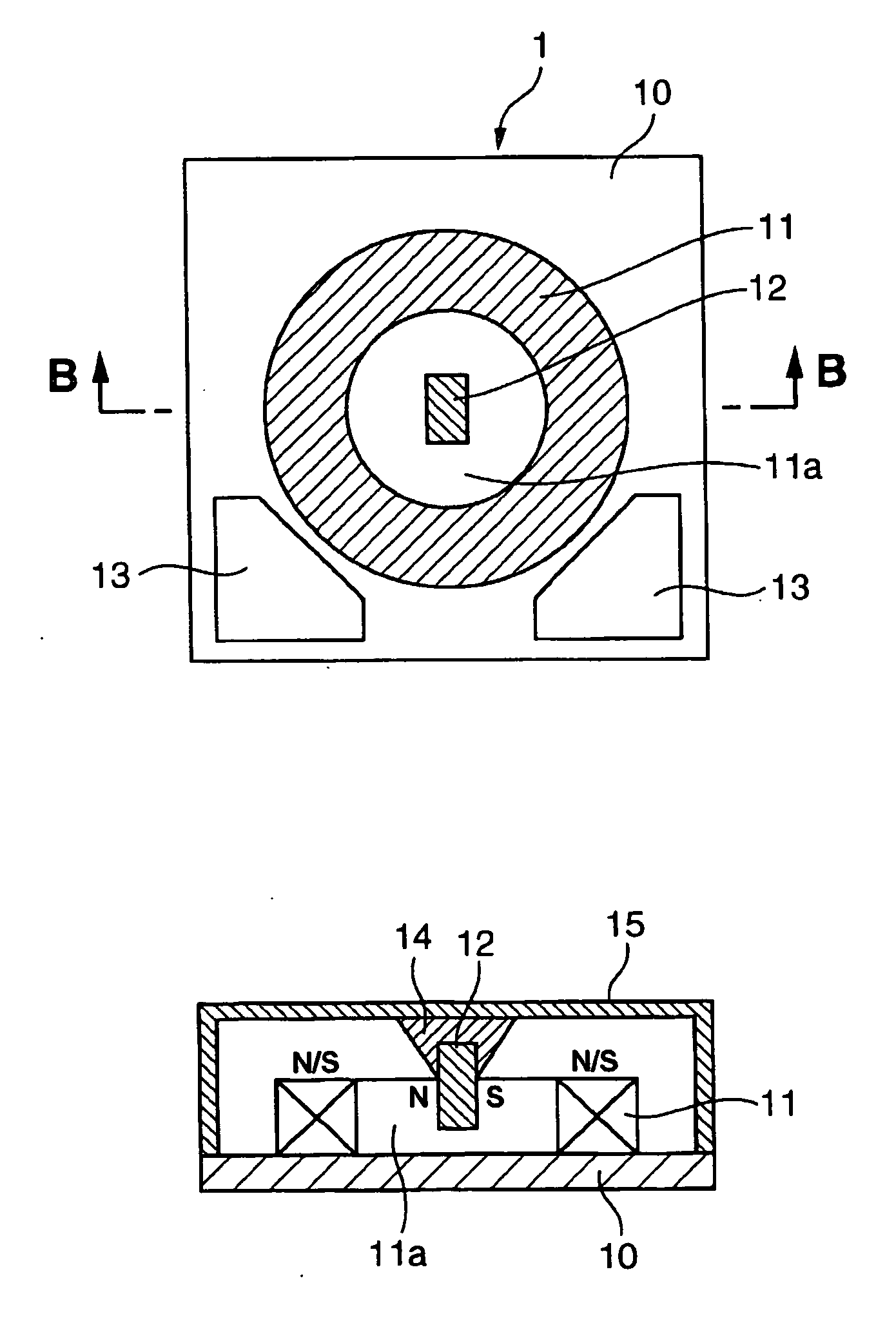
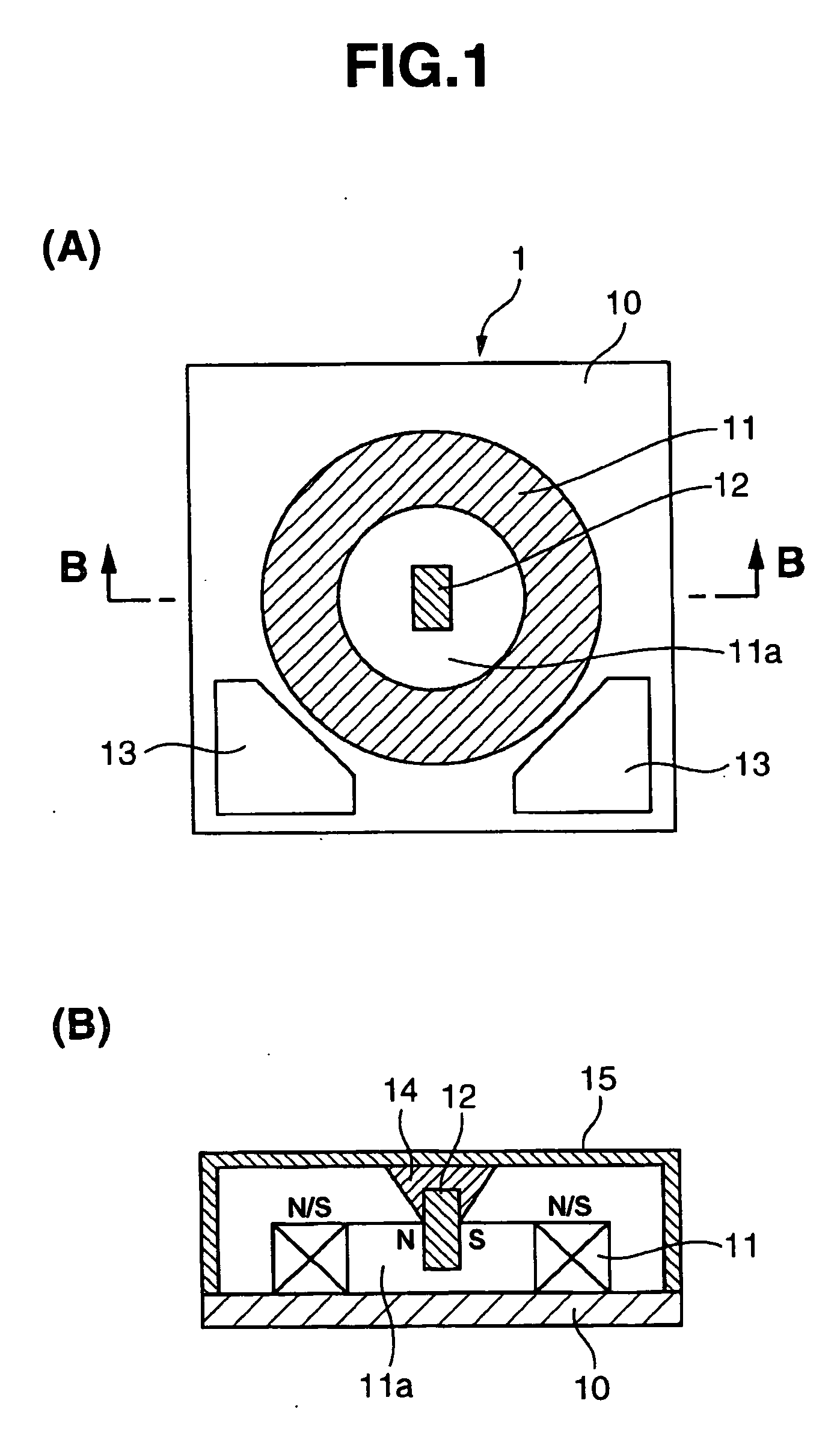
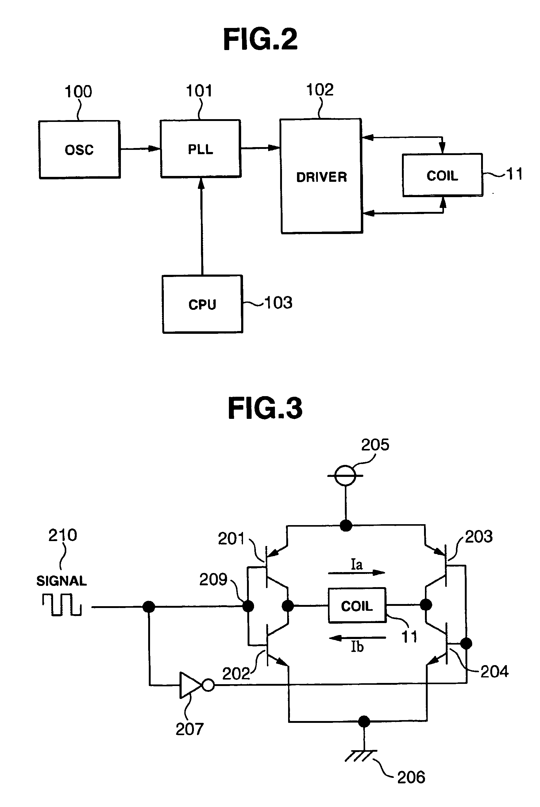
[0080] Foremost, the drive unit pertaining to Embodiment 1 of the present is explained. FIG. 1 is a diagram showing the structure of the drive unit pertaining to Embodiment 1, and FIG. 1(A) is a top view, and FIG. 1(B) is the B-B cross section of FIG. 1(A). FIG. 2 is a circuit structure diagram of the drive unit shown in FIG. 1. FIG. 3 is a circuit structure diagram for driving the coil shown in FIG. 1.

[0081] In FIG. 1(A), the drive unit 1 comprises a substrate 10, a coil 11 for generating magnetism, a permanent magnet 12, and a drive circuit 13 for driving the coil 11. With the coil 11 as the fixed part, one face thereof is mounted on and fixed to the substrate 10. With the permanent magnet 12 as the transducer, one end thereof is retained with a cover as ...

embodiment 2

[0092] Next, the drive unit pertaining to Embodiment 2 of the present invention is explained. FIG. 4 is a cross section of the drive unit pertaining to Embodiment 2. Incidentally, with respect to the structure of the drive unit pertaining to Embodiment 2, points differing from the drive unit pertaining to Embodiment 1 will only be explained, and the structural components that are the same as those of Embodiment 1 are given the same reference numerals.

[0093] In FIG. 4, the difference between the drive unit pertaining to Embodiment 2 and the drive unit pertaining to Embodiment 1 is in that the buffering holder 16 retaining the permanent magnet 12, which is a transducer, is provided to the substrate 10 side and not on the cover 15 side of the case. According to this structure, the permanent magnet 12 will oscillate toward the polar direction with the portion retained by the buffering holder 16 provided on the substrate 10 side as the fulcrum.

[0094] The operation of the drive unit 1 p...

embodiment 3

[0096] Next, the drive unit pertaining to Embodiment 3 of the present invention is explained. FIG. 5 is a cross section of the drive unit pertaining to Embodiment 3. Incidentally, with respect to the structure of the drive unit pertaining to Embodiment 3, points differing from the drive unit pertaining to Embodiment 1 will only be explained, and the structural components that are the same as those of Embodiment 1 are given the same reference numerals.

[0097] In FIG. 5, the difference between the drive unit pertaining to Embodiment 3 and the drive unit 1 pertaining to Embodiment 1 is in that the permanent magnet 12 as a transducer is retained with a buffering supporter 17.

[0098] The operation of the drive unit 1 pertaining to Embodiment 3 is substantially the same as the drive unit 1 pertaining to Embodiment 1, and the detailed description thereof is omitted. With the drive unit 1 pertaining to Embodiment 3, in addition to the effect of the drive unit 1 pertaining to Embodiment 1, t...


PUM

PropertyMeasurementUnit
frequencyaaaaaaaaaa
frequencyaaaaaaaaaa
frequencyaaaaaaaaaa

Abstract

A drive mechanism @is comprised with a set comprising a plurality of magnetic bodies, means for supplying a frequency signal to said set, and means for producing movement caused by the attraction/repulsion between the magnetic bodies. The movement is the driving source of the drive mechanism.

Description

DETAILED DESCRIPTION OF THE INVENTION [0001] 1. Technical Field of the Invention [0002] The present invention pertains to a drive mechanism and drive unit, and in particular to a drive unit structured from a plurality of magnetic materials. Particularly, the present invention relates to a drive mechanism which oscillates a magnetic body and utilizes this as the driving source by adding repulsion or attraction between the magnetic bodies. More particularly, the present invention pertains to an inductive acoustic conversion device, and in particular to a speaker known as a flat speaker or panel speaker. As this flat speaker can be used in sound source generators, portable audio equipment, electronic newspaper audio equipment, PDA audio equipment, underwater audio equipment and supersonic generators, and since it is thin, light and produces high-quality sound, this flat speaker may be disposed as a part of the display face of various display equipment such as a liquid crystal display a...

Claims


Application Information

Patent Timeline
Patent Type & Authority Applications(United States)
IPC IPC(8): G11B5/02B06B1/04G02B7/182G02B26/08H01F7/06H02K33/16H02M7/48H02P25/02H02P25/06H04N5/74H04R1/00H04R1/02H04R3/00H04R7/04H04R9/00H04R9/02H04R9/06H04R11/02H04R11/06
CPCG02B7/1821G02B26/085H01F7/06H01F7/066H02K33/16H04R11/06H02P25/028H04R7/045H04R9/06H04R9/066H04R11/02H02K2201/18H02P25/034Y10S359/904G02B26/08H04R9/00
Inventor TAKEUCHI, KESATOSHI
Owner SEIKO EPSON CORP
Why Eureka
Try Eureka