Methods and apparatuses for transient analyses of circuits

a technology of transient analysis and circuit, applied in the field of automatic circuit analysis, can solve the problems of increasing power dissipation in integrated circuits, increasing power dissipation, and cost of larger power supply currents

Active Publication Date: 2006-02-09
SYNOPSYS INC
View PDF18 Cites 52 Cited by
  • Summary
  • Abstract
  • Description
  • Claims
  • Application Information

AI Technical Summary

Benefits of technology

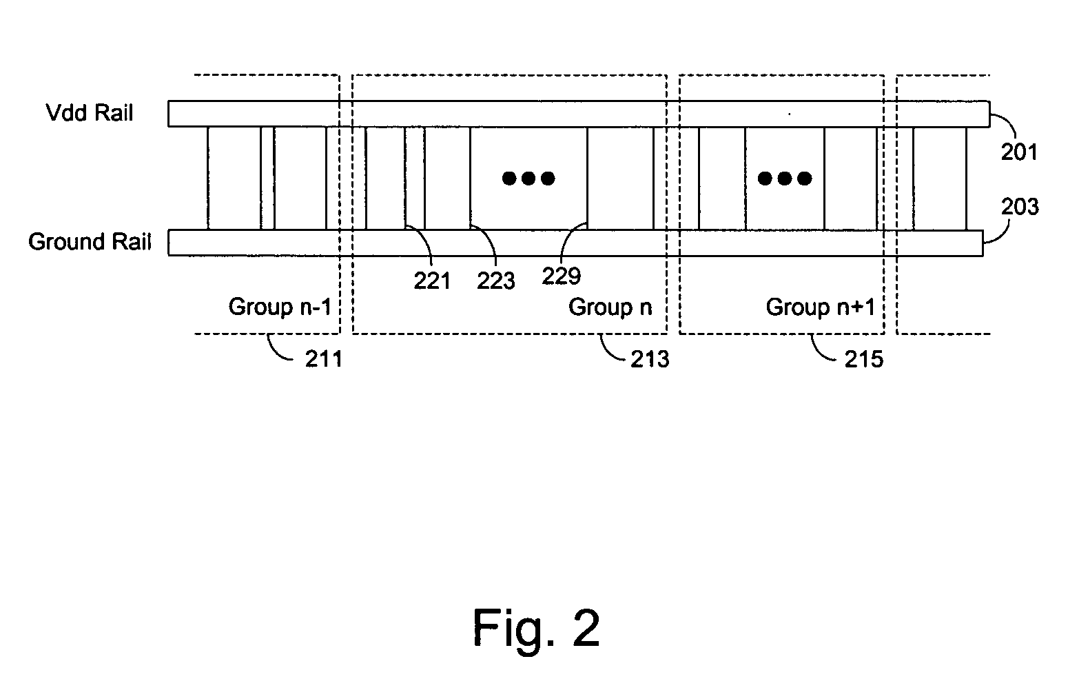
[0016] In one embodiment of the present invention, the cells are grouped locally on the power supply network according to average power dissipation (e.g., so that cell groups have approximately equal power dissipation). A time varying current of each cell group is estimated using a probabilistic approach to represent the cell group so that the probability of a more severe waveform for the current of the cell group is under a certain level. For example, the cells in a group are partitioned as switching cells and non-switching cells using cell toggle rates for the determination of the time varying current. The circuit model of the power supply network includes the current sources according to the estimated time varying currents for the cell groups, the power supply wire resistance, the power supply to ground wire capacitance, well capacitance for cells with wells tied to power supply or ground wires, and the de-coupling capacitance from non-switching cells.
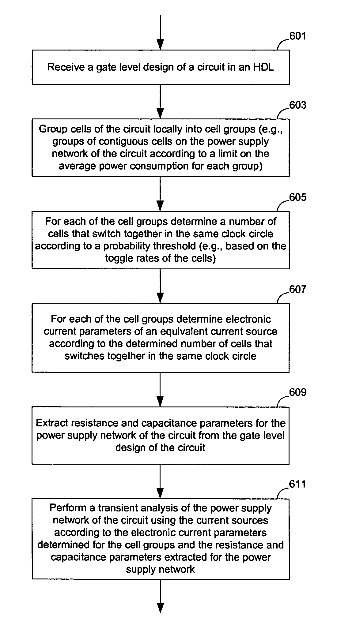
[0017] In one aspect of the present invention, a machine implemented method for circuit analysis includes: grouping cells of a design of a circuit into cell groups according to a threshold for power dissipation; and, determining parameters specifying a time varying current, drawn by each of the cell groups from a power supply network of the circuit, for a transient analysis of the power supply network of the circuit. In one example of an embodiment, the method further includes: performing the transient analysis of the power supply network of the circuit using the parameters specifying the time varying current determined for each of the cell groups. For example, the cells of the design may be grouped locally on the power supply network of the circuit so that cells within each of the cell groups are contiguous on the power supply network of the circuit. The threshold for power dissipation may be used to specify a limit of average power dissipation in each cell group. In one example of an embodiment, the design of the circuit includes a gate level design; and the cells of the design include technology specific standard cells for implementing the circuit on an Integrated Circuit (IC) chip. In one example of an embodiment, at least one of the parameters specifying the time varying current is determined for each of the cell groups using data indicating probabilities of state switching at cells (e.g., toggle rates of cells). In one example of an embodiment, determining the parameters specifying the time varying current includes: estimating a switching current for each cell of each of the cell groups using data specifying energy dissipation at a corresponding cell during a state transition in a clock cycle; and, determining a number of first cells that switch in a same clock cycle for each of the cell groups using the data indicating probabilities of state switching at cells; where the time varying current drawn by each of the cell groups includes at least switching currents for the number of the first cells that switch in a same clock cycle. In one example of an embodiment, the number of the first cells is determined for each of the cell groups such that a probability of more than the number of cells switching in a same clock cycle is less than a threshold value (e.g., 0.9 or 0.99). In one example of an embodiment, the number of the first cells are determined for each of the cell groups to maximize a peak value of the time varying current while the probability of more than the number of cells switching in a same clock cycle is close to the threshold value. In one example of an embodiment, the transient analysis is performed through solving a set of linear equations with a sparse matrix obtained from discretizing a set of ordinary differential equations based on current sources according to the time varying current for each of the cell groups, resistance and capacitance parameters of the power supply network, well capacitance parameters, and decoupling capacitance parameters. The decoupling capacitance parameters of second cells that are not switching are determined for each of the cell groups but excluding the number of the first cells that are switching; the resistance and capacitance parameters of the power supply network and the well capacitance parameters of wells of cells are extracted from the design of the circuit.
[0018] In one aspect of the present invention, a machine implemented method for circuit analysis includes: determining a representation of a first current, drawn by a group of cells from a power supplying network of a circuit in a clock cycle, using data indicating probabilities of state switching at the cells of the group (e.g., toggle rates of the cells), where the representation of the first current specifies the first current as a non-constant function of time in a clock cycle. In one example of an embodiment, the cells are technology specific standard cells for implementing the circuit on an Integrated Circuit (IC) chip. In one example of an embodiment, a first number is determined from the data indicating probabilities of state switching at the cells of the group such that a probability of more than the first number of cells of the group switching in a same clock cycle is about a predetermined value; and then, first cells of the first number are selected from the group to determine the representation of the first current from currents drawn by the first number of the first cells when the first cells switch together in a same clock cycle. In one example of an embodiment, a representation of a second current drawn by one of the cells of the group is determined to specify the second current as a non-constant function of time in a clock cycle in determining the representation of the first current; and the representation of the second current is determined from an amount of energy dissipation in the one of the cells during switching in state in a clock cycle. In one example of an embodiment, equivalent resistance and capacitance parameters for second cells of the group (not including any of the first cells) when the second cells do not switch are further determined. In one example of an embodiment, the group of cells is modeled using at least a current source according to the representation of the first current and the equivalent resistance and capacitance parameters. In one example of an embodiment, the group of cells is further modeled using the well capacitance parameters determined for the cells of the group. In one example of an embodiment, cells of a design of the circuit are selected into the group so that an average power dissipation of the group is at about a predetermined level.

Problems solved by technology

Power dissipation in integrated circuits increases as chip frequencies and die area increase.
Lowering the power supply voltage has mitigated the rapid increase in power dissipation for designs in newer process technologies but at the cost of larger power supply currents.
The voltage drop, if large enough, can cause functional failures.
However, even smaller voltage drops that are only a fraction of the power supply voltage can cause timing errors, because the reduced supply voltage increases the delay of logic gates.
If the increased delays are not accounted for accordingly, the results of chip timing analyses can be erroneous.
Further, large electronic currents can cause failures if the peak current exceeds limits set by the material parameters for the power supply wires.
However, the cells of the circuitry draw time-varying currents from the power supply network in performing state switching activities.
A traditional DC analysis does not provide any transient voltage drop information.
The results of a DC approach are not accurate and could not account for many physical effects such as the placement of de-coupling capacitors or the speed of the transitions of the standard cell outputs.
The actual voltage drop in the power supply network can be much worse than that calculated by the DC analysis because many gates can switch simultaneously, requiring a much larger instantaneous current from the power network than the average current assumed in the DC analysis.
Therefore, the capacitance and inductance of the power supply network cannot be optimized or analyzed using a DC approach, although in reality they can play a critical role in the actual instantaneous voltage drop.
However, whether the logic gates switch simultaneously or in different time windows can produce significantly different power supply voltage drops.
Further, techniques to reduce the peak voltage drop such as the placement and sizing of de-coupling capacitors or different chip packages cannot be analyzed by the traditional DC analysis, since these elements cannot be accounted for in a DC analysis.
The complexity of the transistor level models severely limits the size of the problem that could be solved.
However, these approaches require detailed transistor level analyses of the functional blocks.
Further, these approaches may only be suitable for the circuits that are designed in a hierarchical way with an obvious block structure.
It is difficult to generate input vectors for the efficient simulation of a function block while obtaining a reasonable worst-case switching current for the function block.

Method used


Image

  • Methods and apparatuses for transient analyses of circuits
  • Methods and apparatuses for transient analyses of circuits
  • Methods and apparatuses for transient analyses of circuits

Examples


Embodiment Construction

[0033] The following description and drawings are illustrative of the invention and are not to be construed as limiting the invention. Numerous specific details are described to provide a thorough understanding of the present invention. However, in certain instances, well known or conventional details are not described in order to avoid obscuring the description of the present invention. References to one or an embodiment in the present disclosure are not necessarily references to the same embodiment; and, such references mean at least one.

[0034] At least one embodiment of the present invention merges groups of contiguous cells in such a way that the time-varying behavior is preserved while reducing the number of independent load currents that have to be analyzed to produce accurate results with minimal run time and memory usage. In one embodiment, the time varying switching currents for the cell groups are estimated based on a probabilistic approach without a detailed simulation o...


PUM


Abstract

Methods and apparatuses for transient analyses of a circuit using a hierarchical approach. In one embodiment, the cells are grouped locally on the power supply network according to average power dissipation. A time varying current of each cell group is estimated using a probabilistic approach to represent the cell group so that the probability of a more severe waveform for the current of the cell group is under a certain level. For example, the cells in a group are partitioned as switching cells and non-switching cells using cell toggle rates for the determination of the time varying current. The circuit model of the power supply network includes the current sources according to the estimated time varying currents for the cell groups, the power supply wire resistance, the power supply to ground wire capacitance, well capacitance and the de-coupling capacitance from non-switching cells.

Description

FIELD OF THE TECHNOLOGY [0001] Some embodiments of the present invention relate to automated circuit analyses, and more particularly to the transient analyses of power supply network of a circuit implemented on an Integrated Circuit (IC) chip. BACKGROUND [0002] Power dissipation in integrated circuits increases as chip frequencies and die area increase. Lowering the power supply voltage has mitigated the rapid increase in power dissipation for designs in newer process technologies but at the cost of larger power supply currents. The electronic current supplied by the power supply grid to each standard cell or custom block (such as a memory) on an Integrated Circuit (IC) chip causes a voltage drop in the supply network due the non-zero impedance (resistance, capacitance and inductance). The voltage drop, if large enough, can cause functional failures. However, even smaller voltage drops that are only a fraction of the power supply voltage can cause timing errors, because the reduced ...

Claims


Application Information

Patent Timeline
Patent Type & Authority Applications(United States)
IPC IPC(8): G06F17/50
CPCG06F2217/78G06F17/5081G06F30/398G06F2119/06
Inventor RAHMAT, KHALIDMCELVAIN, KENNETH S.
Owner SYNOPSYS INC
Why Eureka
Try Eureka