Device for igniting an internal combustion engine

a technology for internal combustion engines and combustion engines, which is applied in the direction of engine ignition, combustion engines, machines/engines, etc., can solve the problems of inability to achieve optimal ignition of air/fuel mixtures, and achieve the effect of improving ignition reliability, reducing the tendency to knock, and improving ignition reliability

Inactive Publication Date: 2006-02-16
ROBERT BOSCH GMBH
View PDF10 Cites 13 Cited by
  • Summary
  • Abstract
  • Description
  • Claims
  • Application Information

AI Technical Summary

Benefits of technology

[0002] The device according to the present invention has the advantage that an ignition of the air / fuel mixture takes place at a plurality of points in the combustion chamber through the focusing of the laser beams. The plurality of ignition locations formed in this way improves the reliability of the ignition. An optimal ignition of the air / fuel mixture is not possible at every point in the combustion chamber in all operating states. This fact is counteracted by the spatial distribution of the various ignition locations. In addition, the provision of a plurality of ignition locations generally improves the ignition. Because the paths traveled by the flame front in the combustion chamber are also reduced, the tendency to knock can be significantly reduced. In addition, the plurality of ignition locations shortens the time required for the combustion of the mixture in the combustion chamber, which is advantageous from a thermodynamic point of view.

Problems solved by technology

An optimal ignition of the air / fuel mixture is not possible at every point in the combustion chamber in all operating states.

Method used


Image

  • Device for igniting an internal combustion engine
  • Device for igniting an internal combustion engine

Examples


Embodiment Construction

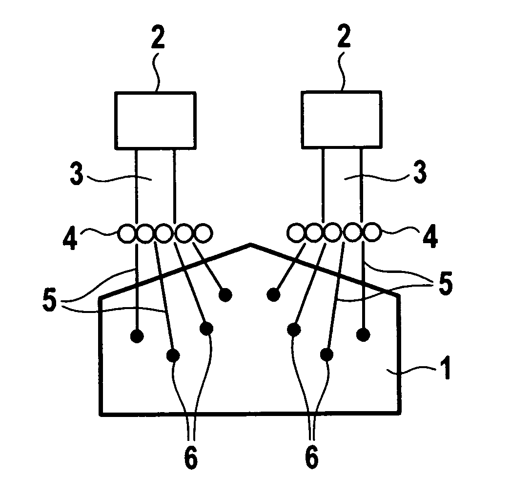
[0005] In FIG. 1, the combustion chamber of an internal combustion engine is schematically designated 1. Such a combustion chamber is the standard combustion chamber of an SI engine as standardly used in today's motor vehicles. Because the details of such engines are generally known, here combustion chamber 1 is indicated only schematically as a closed volume, without indicating further details.

[0006] In order to ignite the air / fuel mixture that has been brought into combustion chamber 1, two laser sources 2 are provided that emit laser radiation 3. Laser radiation 3 is sent through a lens array 4. This divides laser radiation 3 into a plurality of laser sub-beams 5, each of which then focuses in a focus point 6. Focus points 6 are situated in the interior of combustion chamber 1, and are used to ignite the air / fuel mixture in combustion chamber 1. In focus points 6, each of the laser sub-beams 5 is focused onto a very small point, which greatly increases the temperature at this po...


PUM


Abstract

A device for ignition in an internal combustion engine using laser radiation. The laser radiation has a plurality of laser sub-beams that are focused at a plurality of different focus points in the combustion chamber.

Description

BACKGROUND INFORMATION [0001] From German Patent Application No. DE 199 11 737, a device is known for igniting an internal combustion engine in which focused laser radiation is introduced into a combustion chamber of an internal combustion engine. Due to the strong focusing of the laser radiation, in this focus point a temperature results that is so high that the laser radiation causes an ignition of an air / fuel mixture in the combustion chamber. SUMMARY OF THE INVENTION [0002] The device according to the present invention has the advantage that an ignition of the air / fuel mixture takes place at a plurality of points in the combustion chamber through the focusing of the laser beams. The plurality of ignition locations formed in this way improves the reliability of the ignition. An optimal ignition of the air / fuel mixture is not possible at every point in the combustion chamber in all operating states. This fact is counteracted by the spatial distribution of the various ignition loca...

Claims


Application Information

Patent Timeline
Patent Type & Authority Applications(United States)
IPC IPC(8): F02P23/04
CPCF02P23/04
Inventor RIDDERBUSCH, HEIKO
Owner ROBERT BOSCH GMBH
Why Eureka
Try Eureka