Conductive railroad attachment

a technology of conductive rails and rail tracks, applied in rail devices, power rails, ways, etc., can solve problems such as deterioration of electrical connections, frequent maintenance of intermittent electrical connections, and stress concentration of the area of track rails

Active Publication Date: 2006-02-16
CCI THERMAL TECH INC
View PDF4 Cites 15 Cited by
  • Summary
  • Abstract
  • Description
  • Claims
  • Application Information

AI Technical Summary

Benefits of technology

[0017] As will be appreciated, the mechanical anchor maintains the signal conductor in fixed positional relationship with the track rail while the electrically conductive adhesive cures. This allows the conductive adhesive to cure without additional labor requirements. Further, the mechanical anchor may permit the track rail to be utilized by railroad vehicles while the conductive adhesive cures.

Problems solved by technology

In the later regard, electro-galvanic corrosion between the connector and the pigtail cable and / or the signal line may result in a deterioration of the electrical connection over time.
In any case, the presence of such resistance and / or deterioration of the electrical connection can result in intermittent electrical connections that can require frequent maintenance.
Furthermore, if the weld area is not carefully located on the track rail, the presence of Martensite can result in an area of stress concentration within the track rail.
Over time, this area may weaken and / or result in the fracture of the track rail.
In the case of contact clamps, the inventor has recognized that due to corrosion on the surface of the track rail as well as electro-galvanic action between the rail and the clamp, electrical contact between the clamp and the rail is often poor and is subject to deterioration over time.

Method used


Image

  • Conductive railroad attachment
  • Conductive railroad attachment
  • Conductive railroad attachment

Examples


Embodiment Construction

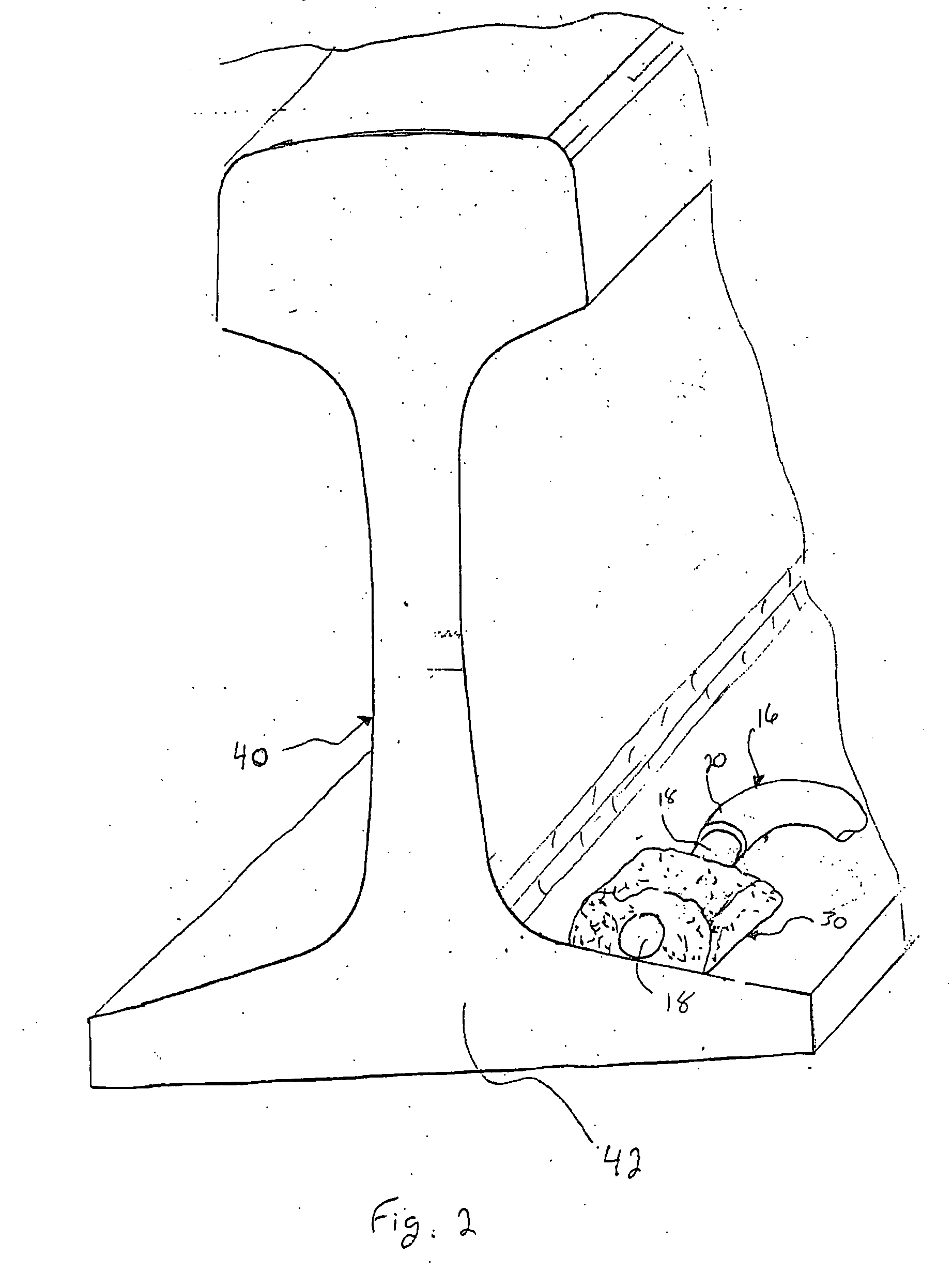
[0029] The present invention is directed to the use of an electrically conductive adhesive to connect a signal conductor to a railroad track rail. Though discussed herein in relation to interconnecting a switching box to track rail via a signal conductor, it will be appreciated that the invention is applicable to the electrical interconnection of any electrical conductor to a track rail for any purpose.

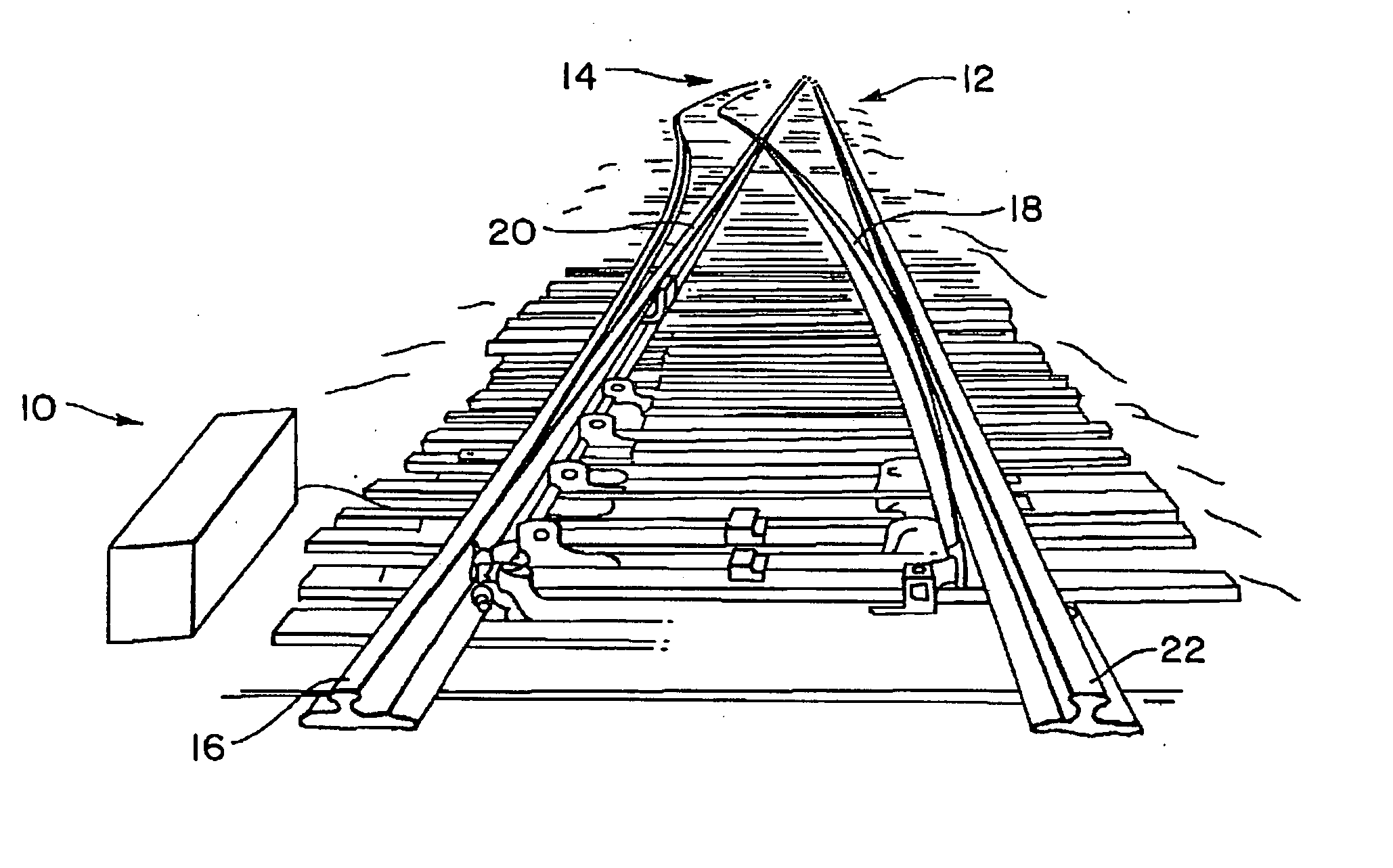
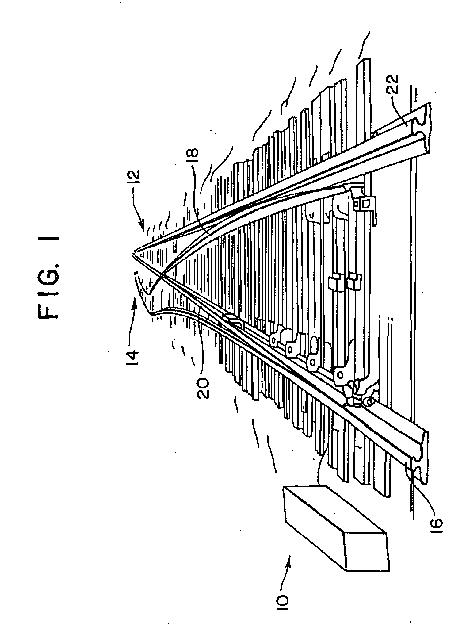
[0030] Referring to FIG. 1, a section of railroad track is generally identified by the reference numeral 10. As shown, the section of railroad track 10 includes a switching mechanism to switch trains between first and second tracks 12, 14. Each set of tracks 12, 14 includes two of track rails. As shown, the first track 12 includes a switching rail 12a and a stationary or stock rail 12b (also known as a running rail). Likewise, the second track 14 includes a stock rail 14a and a switching rail 14b. For purposes of controlling traffic, each track rail 12, 14 is electrically interconnec...


PUM

PropertyMeasurementUnit
temperatureaaaaaaaaaa
electricallyaaaaaaaaaa

Abstract

Disclosed is a method for forming electrical interconnections between railroad track components and signal conductors/lines. In one arrangement, an electrically conductive adhesive is utilized to electrically interconnect a signal conductor to a railroad track component. In another arrangement, a clamp is utilized in conjunction with the electrically conductive adhesive that forms the electrical interconnection. The clamp maintains the signal conductor in direct contact with the surface of the railroad track component while the electrically conductive adhesive cures. In these arrangements, the use of the electrically conductive adhesive allows for making an electrical connection with a railroad component without penetrating the structure of that component. In a further arrangement, a hollow tubular connector is utilized to electrically connect two signal conductors associated with railroad track components. An interior of the tubular connector is at least partially filled with an electrically conductive adhesive prior to inserting the ends of the signal conductors therein.

Description

CROSS REFERENCE TO RELATED APPLICATIONS [0001] This application claims priority under 35 U.S.C. 119 to U.S. Provisional Application No. 60 / 600,182 entitled: “Non-invasive Railroad Attachment Mechanism,” having a filing date of Aug. 10, 2004.FIELD OF THE INVENTION [0002] The present invention relates to a system and method for forming an electrical connection between a railroad track rail and any electrical conductor, for example signal lines, wires or cables. Further, the system is operative to form such an electrical connection for the conduction of any voltage and / or current. BACKGROUND OF THE INVENTION [0003] In typical railroad systems, a length of many miles of track may be divided into a plurality of successive adjacent blocks that may be further subdivided into cut circuits (collectively track sections) for control, monitoring, heating and / or maintenance purposes. Each track section forms a track circuit wherein the track rails are utilized to carry electrical signals. In som...

Claims


Application Information

Patent Timeline
Patent Type & Authority Applications(United States)
IPC IPC(8): B60M1/00
CPCB60M1/30B60M5/00Y10T29/49147Y10T29/49117Y10T29/49149Y10T29/49146
Inventor REICHLE, DAVID L.
Owner CCI THERMAL TECH INC
Why Eureka
Try Eureka