Multi-function field-deployable resource harnessing apparatus and methods of manufacture

a multi-functional, resource-harnessing technology, applied in reverse osmosis, lighting and heating apparatus, instruments, etc., can solve the problems of plurality of losses, plurality of losses, and significant more limited utility and application limitations

Inactive Publication Date: 2006-02-16
ESSIG JR JOHN R +1
View PDF20 Cites 294 Cited by
  • Summary
  • Abstract
  • Description
  • Claims
  • Application Information

AI Technical Summary

Problems solved by technology

In contrast, all related art is of a substantially fixed configuration (i.e., non-re-reconfigurable) and, thus, is significantly more limited with respect to utilities and applications thereof.
In contrast, most related art requires sunlight or other electromagnetic radiation to pass through the transparent membrane of a super-ambient reflector chamber on its way to and from the reflector, thereby resulting in a plurality of losses.
The remaining related art, although utilizing a sub-ambient pressure reflector chamber, also require...

Method used


Image

  • Multi-function field-deployable resource harnessing apparatus and methods of manufacture
  • Multi-function field-deployable resource harnessing apparatus and methods of manufacture
  • Multi-function field-deployable resource harnessing apparatus and methods of manufacture

Examples


first embodiment

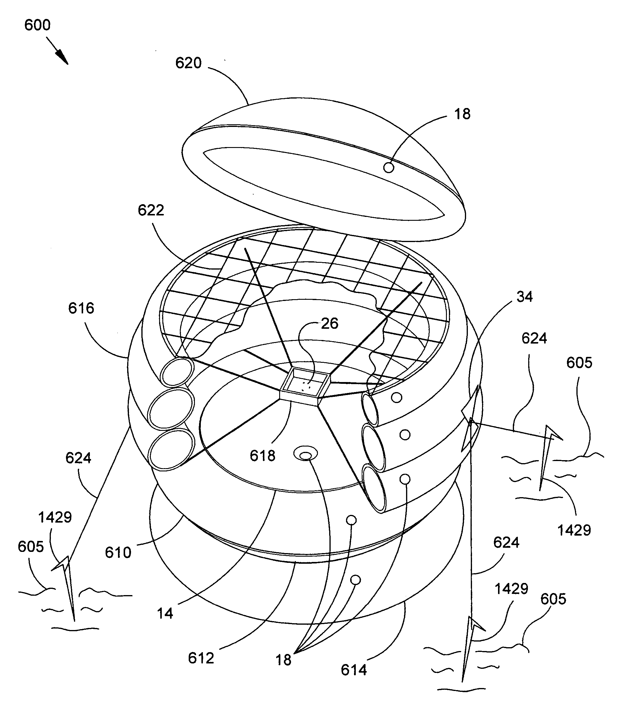
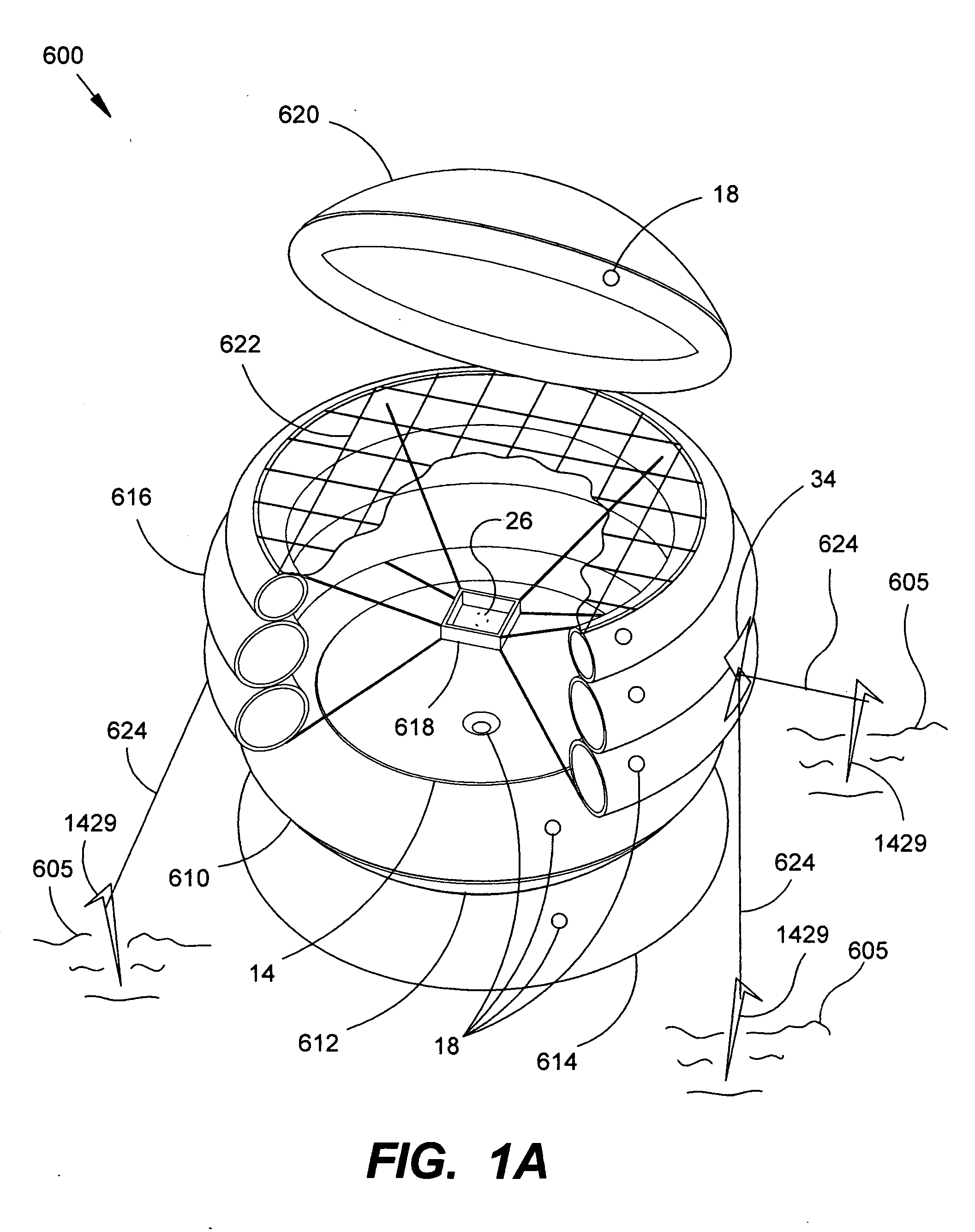
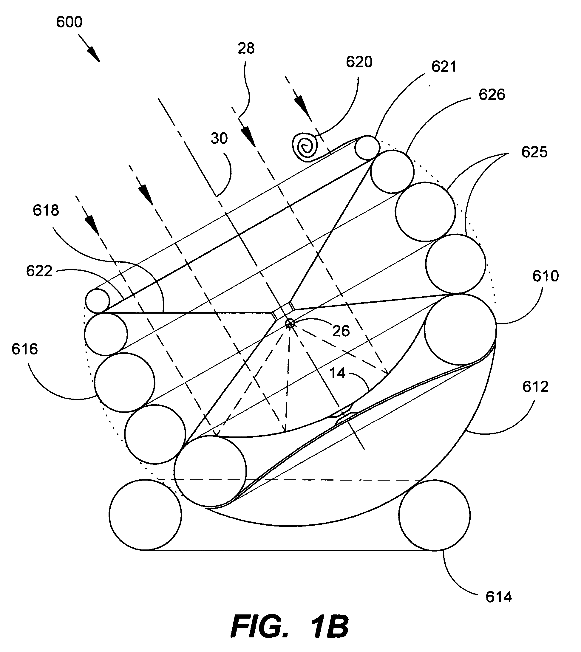
[0194]FIG. 1A depicts a typical selectably deployable, modular, inflatable, multifunction, field-deployable apparatus 600 comprising as its primary functional element a basic inflatable multifunction reflector apparatus 610 in a preferred first embodiment configuration. The apparatus 610 is shown optionally supported on its lower side by a removably (i.e., separably) attached inflatable spherical support 612, which is movably couched within an optional separate inflatable toroidal ring 614. The apparatus 610 is shown supporting on its upper side an optional removably attached inflatable safety shield 616 (shown partially cut away) or safety cage (or other safety member) that further supports an optional removably attached cable-stayed support 618 for holding various items, materials, and / or accessory elements (not shown) in proximity to the focal point 26 of the basic reflector apparatus 610.

[0195] In addition to the safety shield 616, two other safety devices or means are shown for...

second embodiment

FIGS. 4A-I: Description and Operation of the Basic Inflatable Reflector Apparatus—Second Embodiment

[0224] In FIGS. 4A and 4B, the second main embodiment device 386 is illustrated as an inflated toroid or ring support element 400 supporting an upper transparent membrane 388 and a lower reflective membrane 390. The transparent membrane 388 and reflective membrane 390 provide a central reflector chamber (i.e., pressure envelope) 392 with a double parabolic convex-convex lens configuration when inflated to a super-ambient pressure. The transparent membrane 388 has a centered inflation valve 18 for inflating the reflector chamber 392; however, it is noted that the inflation valve 18 may alternatively be located at any other useful location such as in the reflective membrane 390. The inflatable toroidal support element 400 also has a valve 18 for inflation to form a rigid ring. Two valves are shown for separate inflation of the ring support 400 and the reflector chamber 392; however, it i...

third embodiment

FIGS. 4K-O: Description and Operation of a Simplified Inflatable Reflector Apparatus—Third Embodiment

[0232] FIGS. 4K-O illustrate the construction and use of simplified alternate inflatable reflector apparatuses (third main embodiment) having only one membrane shown attached to an inflatable (or, optionally, otherwise collapsible or rigid) support element.

[0233]FIG. 4K depicts an alternate simple planar reflector or mirror apparatus 1510 provided by attaching as few as one planar (i.e., non-preformed) reflective membrane 1512 to the support ring 400. Although such an apparatus having only a single membrane is generally not operable as a single apparatus to concentrate electromagnetic energy, the apparatus 1510 can effectively serve as a highly portable self-imaging mirror, a photographic light reflector and / or diffuser, and / or a radiant electromagnetic energy heat shield (such as to shield a person object, or other item from radiant energy emitted from a fireplace, campfire, of oth...


PUM


Abstract

A multi-function, field-deployable resource harnessing apparatus 600 having, in its embodiments, an inflatable reflector apparatus 610 comprising a least one manufactured parabolic mirror made from a pressure-deformable reflective covering of an inflatable ring for focusing electromagnetic energy from radio frequency radiation (RF) through the ultraviolet (UV) radiation including solar energy for (1) heating and cooking, (2) electrical power generation, (3) enhancing the transmission and reception of radio signals, (4) enhancing vision in low-light environments, and/or (5) projection of optical signals or images. The device also has non-electromagnetic uses, such as the collection and storage of water, harnessing of energy from a fluid stream, and/or harnessing wave energy. A first main embodiment of the inflatable reflector apparatus 610 generally utilizes two pressure-deformable membranes, at least one of which is reflective. A second main embodiment utilizes a reflective membrane and a transparent membrane. In addition to the reflector apparatus 610, the modular apparatus 600 typically further includes modular assemblies to increase versatility, facilitate use, and/or enhance safety such as, for example, a modular support and orienting assembly 612, a separate support ring 614, a safety shield or cage 616, a focal point support assembly 618, a safety cover 620, a safety net or mesh 622, and a stabilizing assembly 624. Portability is enhanced by complete collapsing of the inflatable device.

Description

CROSS-REFERENCE TO RELATED APPLICATIONS [0001] This application claims the benefit of U.S. Provisional Patent Application Ser. No. 60 / 620,510 filed 20 Oct. 2004. This application also claims the benefit of PCT Patent Application Serial No. PCT / US2004 / 040479 filed 6 Dec. 2004. This application further claims the benefit of U.S. Provisional Patent Application of John R. Essig Jr and James M Essig for “Concentrating Reflector Apparatus with Safety Device and Methods of Use” filed 11 Oct. 2005, for which a serial number has not yet been assigned. This application is a continuation-in-part (CIP) of U.S. patent application Ser. No. 10 / 729,145 filed 4 Dec. 2003, which is a continuation-in-part of U.S. patent application Ser. No. 10 / 156,814 filed 30 May 2002, now U.S. Pat. No. 6,897,832 issued 24 May 2005. [0002] This application also is related in subject matter to US Design Patent Applications filed 29 Nov. 2002 having Ser. Nos. 29 / 171799, 29 / 171800, 29 / 171801, 29 / 171800, 29 / 171801, now, ...

Claims


Application Information

Patent Timeline
IPC IPC(8): H01Q15/14B01D61/06F24S23/00C02F1/14C02F1/44F24S23/71G10K11/28H01Q15/16
CPCB01D61/06C02F1/14C02F1/441G10K11/28H01Q15/163Y02E10/47Y02W10/33Y02W10/37A01K61/60Y02A20/212F24S20/80F24S23/715Y02A40/81Y02P60/60Y02E10/40
Inventor ESSIG, JOHNESSIG, JAMES
Owner ESSIG JR JOHN R
Why Eureka
Try Eureka