
Electrochemical device and method for manaufacturing same

a technology of electrochemical devices and electrode plates, which is applied in the direction of wound/folded electrode electrodes, sustainable manufacturing/processing, and primary cell maintainance/servicing, etc., can solve the problems of affecting the reliability of electrochemical devices, limiting the improvement of electrical capacity per volume of devices, and affecting the homogeneous electrode reaction. , to achieve the effect of simple structure, high reliability and high electrical capacity

Inactive Publication Date: 2006-02-16
PANASONIC CORP
View PDF12 Cites 60 Cited by
  • Summary
  • Abstract
  • Description
  • Claims
  • Application Information

AI Technical Summary

Benefits of technology

[0008] The present invention is achieved in view of the circumstances described above. The present invention can provide an electrochemical device with a simple structure, high reliability and high electrical capacity. Also, the present invention can efficiently manufacture a plurality of electrochemical devices at the same time.
[0019] In the electrochemical device, it is preferred that the current collector sheet with the conductive area and the insulating area have a first edge that comprises a part of the conductive area and that does not carry the electrode mixture layer, that the conductive area be connected to the first terminal or the second terminal at the first edge, and that at least a part of the first edge be buried in the first terminal or the second terminal. This structure makes it possible to obtain high current collecting performance. On the other hand, in the case of a structure of using a current collector plate and connecting the edge of an electrode to the current collector plate, the contact area of the electrode and the edge becomes small, so that the current collecting performance tends to lower in comparison with the above structure. Further, when an electrode mixture layer of low conductivity is brought into contact with a current collector plate, the current collecting performance tends to become insufficient in comparison with the above structure.
[0021] When the electrode plate assembly further has a third side face and a fourth side face, it is preferred that an edge of the first current collector sheet, an edge of the second current collector sheet, and an edge of the separator be substantially flush with one another on each of the first side face, the second side face, the third side face, and the fourth side face. It is also preferred that an area S(1) per one side of the first current collector sheet, an area S(2) per one side of the second current collector sheet, and an area S(s) per one side of the separator satisfy the following relations: S(1)≦S(s)≦S(1)×1.05, and S(2)≦S(s)≦S(2)×1.05. This simple and balanced structure increases the volume efficiency of the electrochemical device, while enhancing its reliability.

Problems solved by technology

However, currently available electrochemical devices have a complicated internal structure, so that there is a limit to improvements in electrical capacity per a given volume of a device.
Complicated structure prevents improvements in reliability of electrochemical devices in some aspects.
For example, a current-collecting tab or lead connected to an electrode may interfere with a homogeneous electrode reaction in the plane of the electrode.
However, in such cases where the positive electrode is caused to protrude from one side face of the electrode plate assembly and the negative electrode is caused to protrude from the side face opposite the above-mentioned side face, the manufacturing process of the electrode plate assembly becomes complicated.
Accordingly, electrode plate assemblies need to be produced one by one, thereby having a problem of being unable to manufacture a plurality of electrode plate assemblies at the same time.

Method used


Image

  • Electrochemical device and method for manaufacturing same
  • Electrochemical device and method for manaufacturing same
  • Electrochemical device and method for manaufacturing same

Examples


embodiment 1

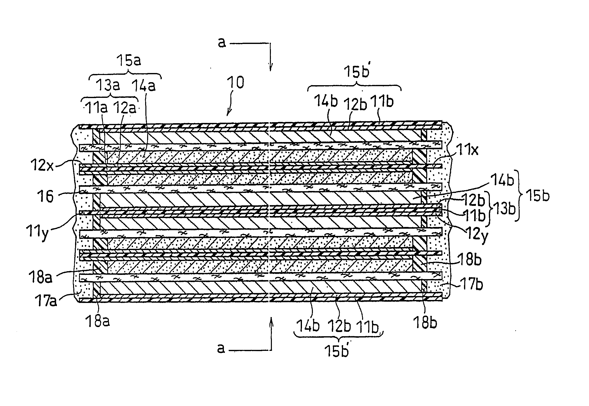
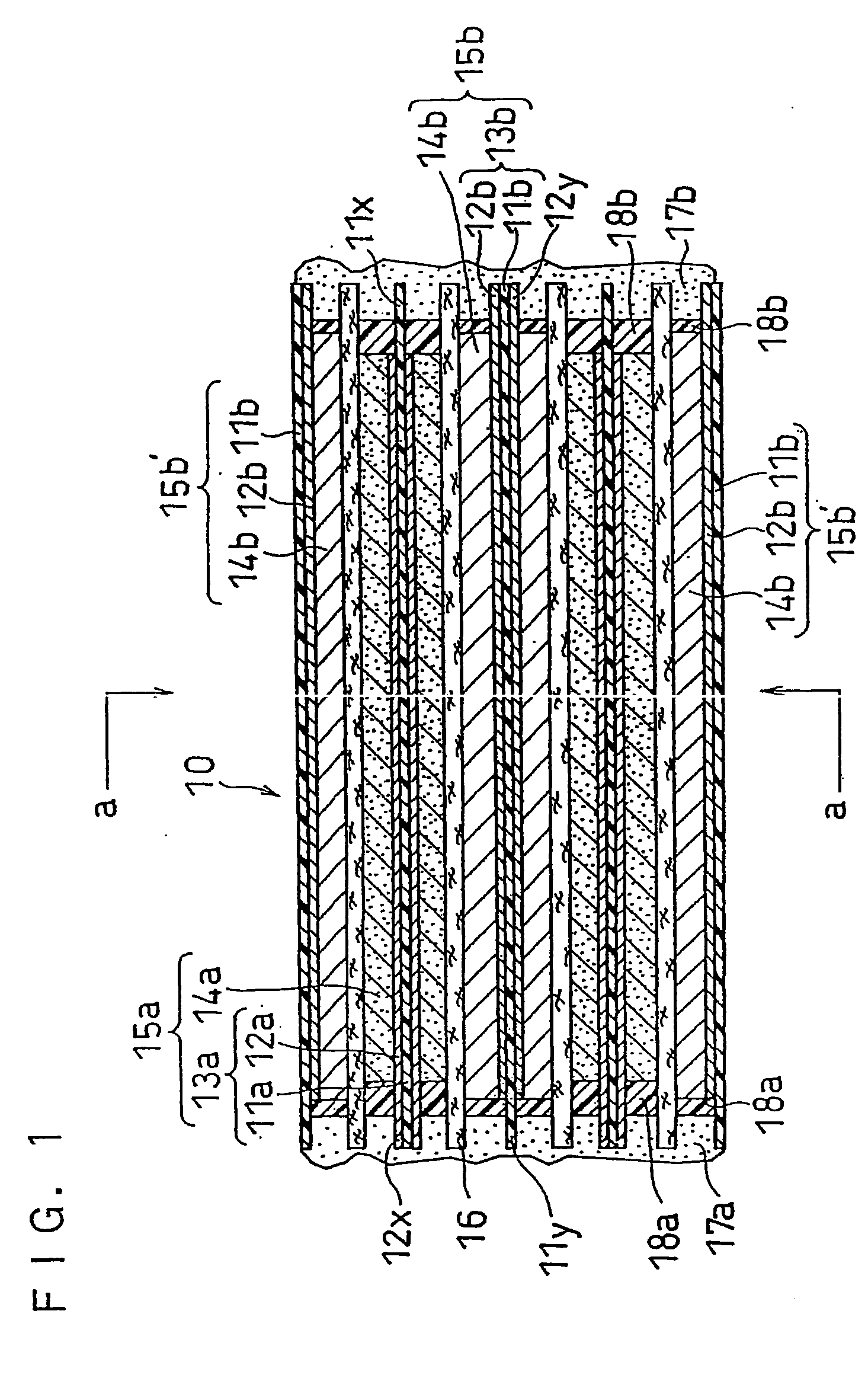
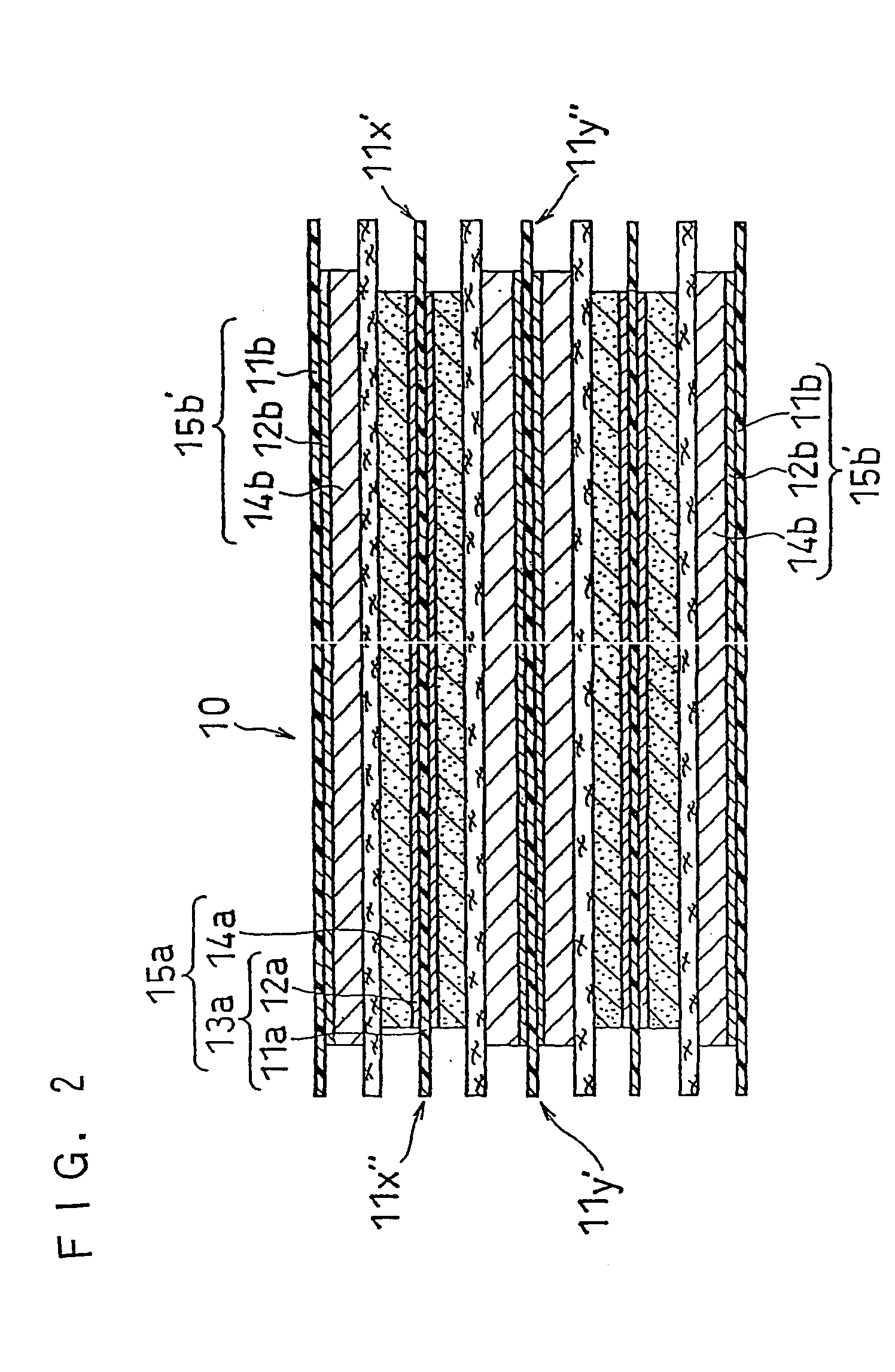
[0100]FIG. 1 shows a longitudinal sectional view of an exemplary layered-type electrode plate assembly according to the present invention. FIG. 2 shows an a-a line sectional view of the electrode plate assembly. An electrode plate assembly 10 includes a plurality of first electrodes 15a and a plurality of second electrodes 15b which are layered alternately, with a separator 16 interposed between each first electrode 15a and each second electrode 15b.

[0101] The first electrode 15a comprises a first current collector sheet 13a and two first electrode mixture layers 14a, and the first current collector sheet 13a is composed of a resin sheet 11a and a conductive layer 12a of a predetermined pattern formed on each side of the resin sheet 11a. The surface of the conductive layer 12a is a conductive area of the first current collector sheet, while the exposed part of the resin sheet 11a is an insulating area.

[0102] The conductive layer 12a is provided on the whole surface of the first cu...

embodiment 2

[0158] An exemplary wound-type electrode plate assembly is described. FIG. 4 is a schematic longitudinal sectional view of a part of a wound-type electrode plate assembly 30, featuring a first electrode. The material mixture layer and the current collector sheet that are located outside are omitted.

[0159] The wound-type electrode plate assembly 30 includes a first electrode 3a and a second electrode 3b that are layered and wound with a separator 39 interposed between the first electrode 3a and the second electrode 3b.

[0160] The first electrode 3a comprises a first current collector sheet 31a and two first electrode mixture layers 32a on both sides of the first current collector sheet 31a, and the first current collector sheet 31a is composed of a resin sheet and a conductive layer formed on each side of the resin sheet. The surface of the conductive layer is a conductive area of the first current collector sheet, while the exposed part of the resin sheet is an insulating area.

[01...

embodiment 3

[0173] Referring now to FIG. 5, an exemplary method for producing a plurality of layered-type electrode plate assemblies at the same time is described. According to the following method, it is possible to efficiently produce electrode plate assemblies that are, for example, 1 to 300 mm in length, 1 to 300 mm in width, and 0.01 to 20 mm in thickness.

[0174] The production method of this embodiment includes the steps of:

[0175] (a) forming conductive layers on both sides of two insulating base material sheets, based on a predetermined pattern, to obtain a first current collector sheet and a second current collector sheet;

[0176] (b) forming a plurality of first electrode mixture layers and a plurality of second electrode mixture layers on each of the conductive layers of the first current collector sheet and the second current collector sheet, respectively, with a gap therebetween, based on the above-mentioned pattern, to obtain a group of first electrodes and a group of second electr...


PUM

PropertyMeasurementUnit
melting pointaaaaaaaaaa
widthaaaaaaaaaa
widthaaaaaaaaaa

Abstract

An electrochemical device having an electrode plate assembly. The electrode plate assembly includes (a) at least one first electrode, (b) at least one second electrode, and (c) a separator interposed between the first electrode and the second electrode. The first electrode includes a first current collector sheet and at least one first electrode mixture layer carried thereon. The second electrode includes a second current collector sheet and at least one second electrode mixture layer carried thereon. At least one of the first current collector sheet and the second current collector sheet has a conductive area and an insulating area.

Description

TECHNICAL FIELD [0001] The present invention relates to electrochemical devices, and particularly, to improvements in the electrode plate assembly of high energy-density secondary batteries, such as lithium ion secondary batteries. BACKGROUND ART [0002] With the reduction in size and weight of electronic and electric devices, there is an increasing demand for reductions in size and weight of electrochemical devices, such as secondary batteries. However, currently available electrochemical devices have a complicated internal structure, so that there is a limit to improvements in electrical capacity per a given volume of a device. [0003] Complicated structure prevents improvements in reliability of electrochemical devices in some aspects. For example, a current-collecting tab or lead connected to an electrode may interfere with a homogeneous electrode reaction in the plane of the electrode. In the event that a cut section of the lead has metallic burrs that are larger than usual, an i...

Claims


Application Information

Patent Timeline
Patent Type & Authority Applications(United States)
IPC IPC(8): H01M4/64H01M2/16H01M4/13H01M4/66H01M4/70H01M6/42H01M6/50H01M10/04H01M10/0525H01M10/0587H01M10/36H01M10/42H01M50/107H01M50/586
CPCH01M2/0207H01M2/022H01M2/34H01M4/13H01M4/66H01M4/667Y02T10/7011H01M10/0431H01M10/0436H01M10/0525H01M10/0587Y02E60/122H01M4/70Y02E60/10H01M50/107Y02P70/50H01M50/586H01M10/058
Inventor NISHIMURA, KENARAI, NAOTOOSHIMA, TORUDAIO, FUMIOIKOMA, MUNEHISASAITO, NORIOKAIYA, HIDEO
Owner PANASONIC CORP
Learn More