Engine belt-driven system

a belt-driven system and engine technology, applied in the direction of machines/engines, mechanical equipment, machine/engines, etc., can solve the problems of lowering the durability of the alternator, requiring a mass as large as about one tenth of the alternator, and the unstable of the vehicle engine, so as to sacrifice the durability of the vehicle alternator, and improve the stability of the engine belt-driven system

Inactive Publication Date: 2006-02-16
DENSO CORP
View PDF12 Cites 8 Cited by
  • Summary
  • Abstract
  • Description
  • Claims
  • Application Information

AI Technical Summary

Benefits of technology

[0028] With the present invention, it is possible to improve the stability of engine belt-driven system without a sacrifice of the durability of the vehicle alternator, because the vehicle generator having a large inertial moment is provided with the dynamic absorber, and the dynamic absorber has a small inertial moment, so that the constituent elements of the dynamic absorber can be made to have large safety margins.

Problems solved by technology

It was a big challenge to reduce the engine vibration for the purpose of stabilizing the engine belt-driven system, thereby providing quiet vehicles.
It was known that the vehicle engine becomes unstable when a vehicle auxiliary having a large inertia moment exhibits low behavioral stability in the engine belt-driven system.
However, the method (1) had a problem in that it requires a mass as large as about one tenth of the alternator.
Also it lowered the durability of the alternator, because the alternator was attached with a substantial mass at a portion distant from its mass center, that results in the alternator bending.
It was practically impossible to perform such a numerical analysis even by use of a computer.
Hence, if the alternator is driven with the step-up ratio as large as between 2 and 3, the equivalent inertia moment of the alternator becomes the largest factor in the unstableness of the engine belt-driven system.
Especially, in the serpentine belt-driven system where a plurality of auxiliaries are driven through the same belt, its instability becomes worse, because the serpentine belt system is a multi-axis system, and has as many resonance points as there are axes (auxiliaries).
As a result, the rotational speed variation and belt flapping in the case of using the V-ribbed belt becomes more serious than the case of using the conventional V-belt.
Engine belt-driven systems using such a V-ribbed belt have a problem in that it is difficult to provide a space large enough to accommodate the one-way clutch or elastic member as explained with reference to FIG. 9 or FIG. 10 within the alternator, and accordingly it is difficult to use the method (2), because the outer diameter of the pulley of the alternator is made small when the alternator is designed to be driven by the V-ribbed belt.
Accordingly, in the case of the V-ribbed belt pulley, it is difficult for the one-way clutch and the spring to have enough cross-sectional areas, though they are applied with torque larger than in the case of the V-belt pulley.
However, it involves a problem of wear in sliding portions.
In addition, it requires detailed and laborious spring design, which removes the advantage of the method (2) in design ease.

Method used


Image

  • Engine belt-driven system
  • Engine belt-driven system
  • Engine belt-driven system

Examples


first embodiment

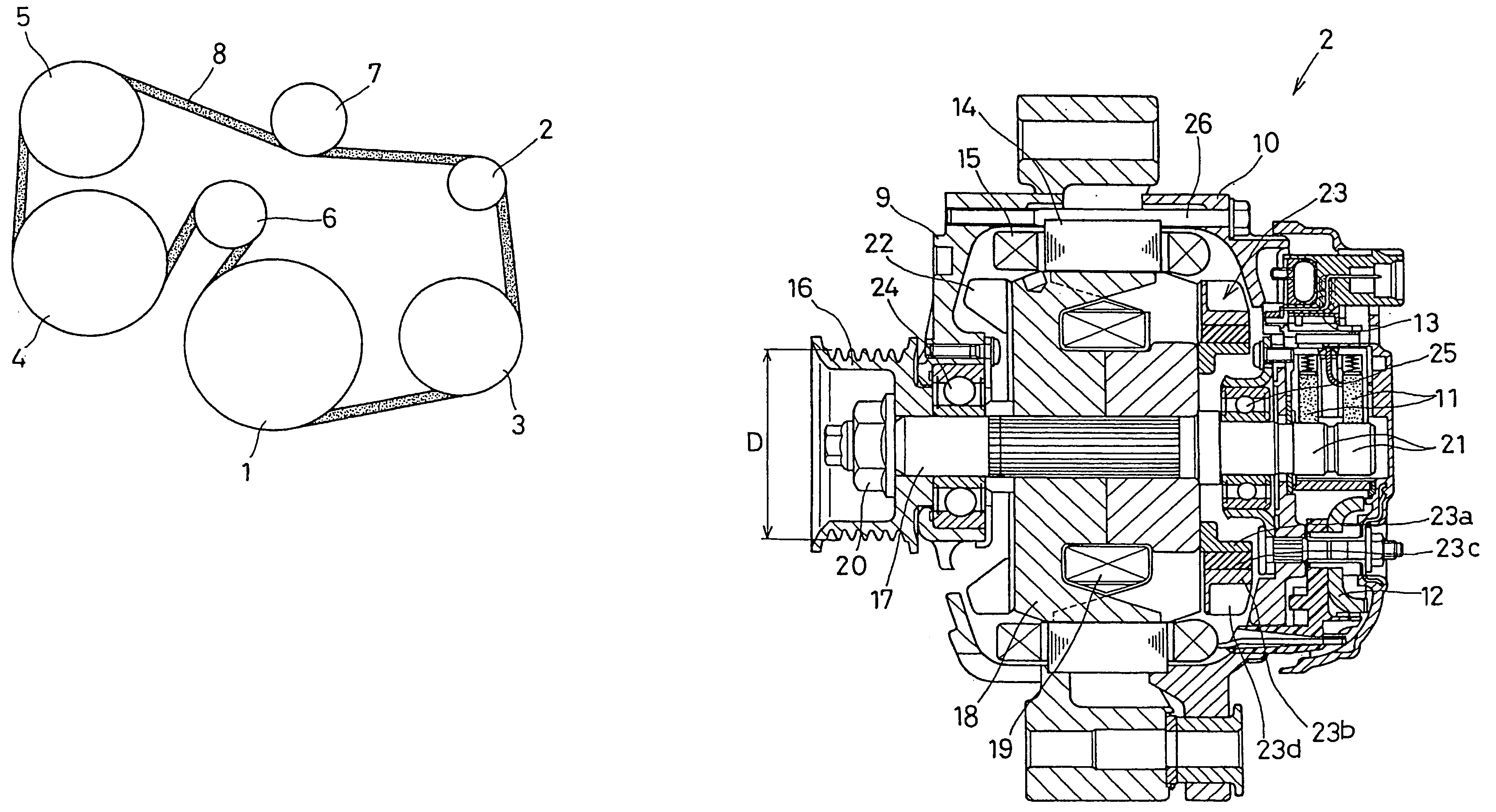
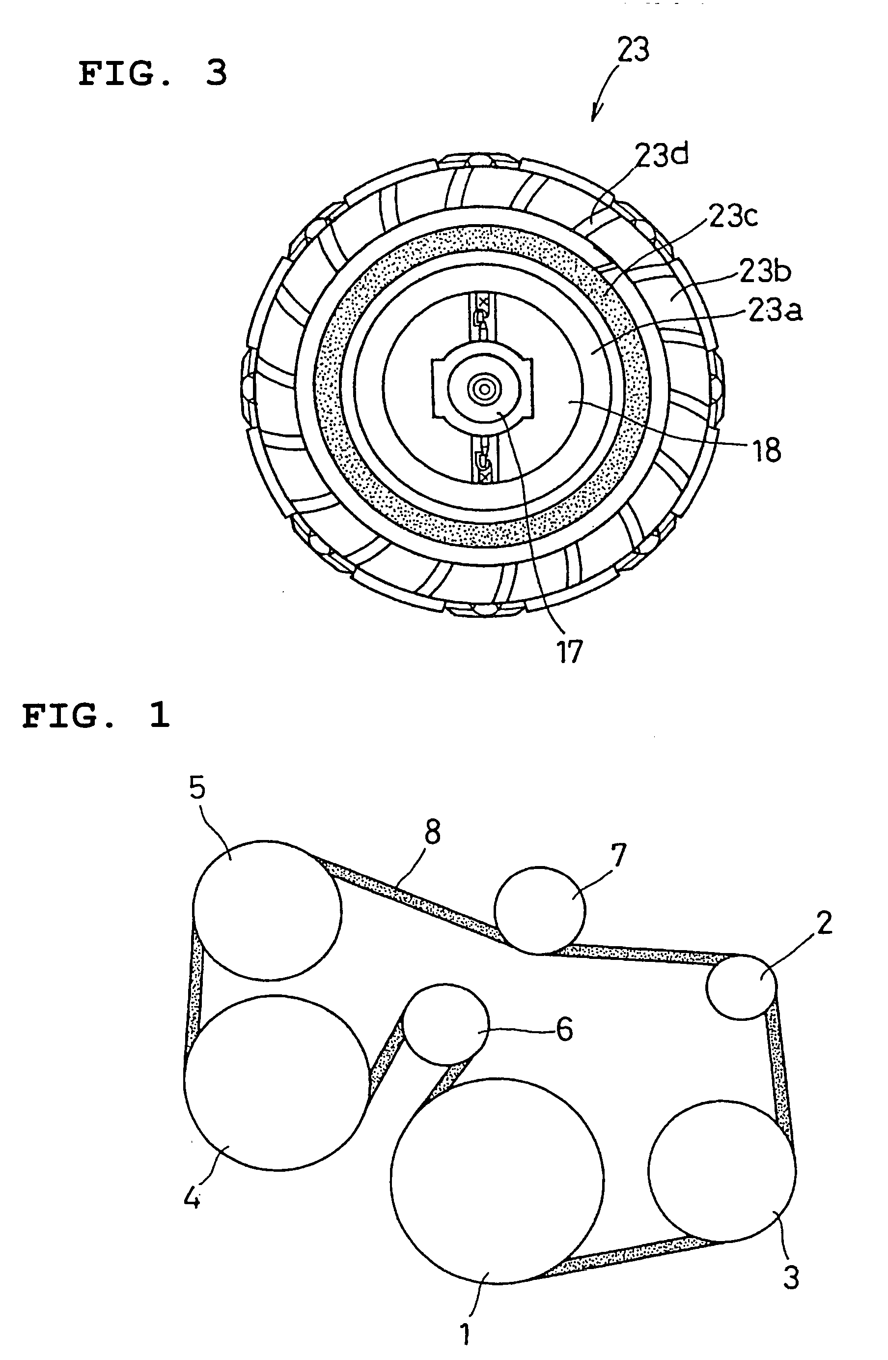
[0040]FIG. 1 is a layout diagram of an engine driven system according to a first embodiment of the invention. The engine driven system includes an alternator 2, an air conditioner compressor 3, a water pump 4, and a power steering hydraulic pump 5 as auxiliaries which are belt-driven by a vehicle engine 1. The engine driven system further includes an auto tensioner 6, and a V-ribbed belt 8 which couples pulleys of these auxiliaries to a crank pulley of the engine 1. This engine driven system is a serpentine belt-driven system.

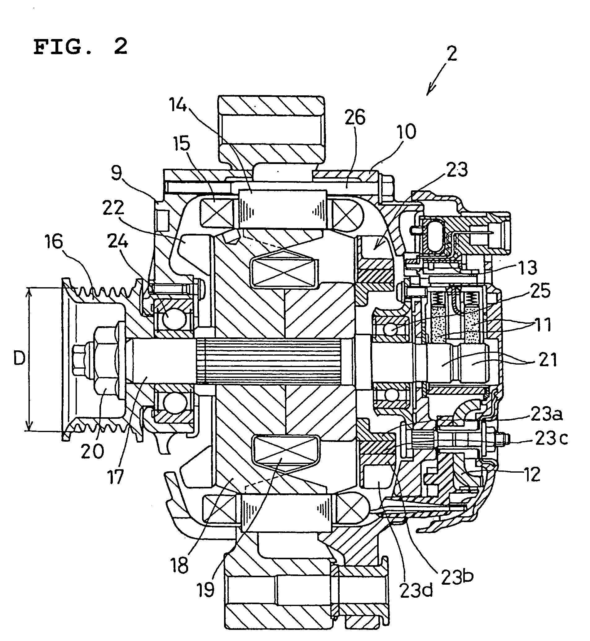
[0041]FIG. 2 is a cross-sectional view of the alternator 2. The alternator 2 includes a stator, a rotor, a front housing member 9, a rear housing member 10, a brush 11, a rectifier 12, and a voltage regulator 13. The stator includes an annular stator core 14, and an armature winding 15 wound around the stator core 14. When the rotor rotates, an AC voltage is induced in the armature winding 15.

[0042] The rotor includes a rotating shaft 17 to which the rotation...

second embodiment

[0080]FIG. 5 is a cross-sectional view of an alternator 2 of an engine driven system according to a second embodiment of the invention. As shown in this figure, the alternator 2 of this embodiment has two dynamic absorbers 23 mounted to the both end surfaces of the rotor corer 18.

[0081] The alternator 2 of this embodiment has a still higher durability, because the inertia moment is spread to the both sides of the rotor core 18.

[0082] Incidentally, in this embodiment, it is necessary to change the spring constants of the dynamic absorbers 23 according to their masses.

[0083] The alternator of this embodiment has good self-cooling performance, since each of the dynamic dampers 23 has fan blades 23.

third embodiment

[0084]FIG. 6 is a partial cross-sectional view of an alternator 2 of an engine driven system according to a third embodiment of the invention. In the third embodiment, a torsion spring 23e is used as the elastic member of the dynamic absorber 23.

[0085] The spring 23e is configured to increase its tightness when compressed to have hysteresis characteristics. The dynamic absorber 23 is excellent at heat resistance, because it can be made of only metals.


PUM


Abstract

The engine belt-driven system includes a plurality of auxiliaries including a vehicle generator, and a V-ribbed belt transmitting torque from a vehicle engine to said plurality of said auxiliaries. The vehicle generator is provided with a dynamic absorber having an inertia moment smaller than an inertia moment of a rotor of said vehicle generator. The dynamic absorber may be mounted to an end surface of the rotor.

Description

CROSS-REFERENCE TO RELATED APPLICATION [0001] This application is related to Japanese Patent Application No. 2004-230742 filed on Aug. 6, 2004, the contents of which are hereby incorporated by reference. BACKGROUND OF THE INVENTION [0002] 1. Field of the Invention [0003] The present invention relates to an engine belt-driven system in which a plurality of auxiliaries including a vehicle alternator (vehicle generator) are belt-driven by a vehicle engine. [0004] 2. Description of Related Art [0005] It was common that a vehicle auxiliary such as a vehicle alternator (referred to as simply alternator hereinafter) is driven by a vehicle engine through a V-belt having a V-shaped cross section, and that the alternator is driven with a step-up ratio of at most 2 because of belt slippage. It was a big challenge to reduce the engine vibration for the purpose of stabilizing the engine belt-driven system, thereby providing quiet vehicles. [0006] It was known that the vehicle engine becomes unst...

Claims


Application Information

Patent Timeline
Patent Type & Authority Applications(United States)
IPC IPC(8): F16H61/00F16H59/00
CPCF02B67/06H02K9/06H02K5/24F16F15/1442
Inventor UMEDA, ATSUSHISHIGA, TSUTOMUIHATA, KOUICHI
Owner DENSO CORP
Why Eureka
Try Eureka