Ultrasound diagnostic apparatus and ultrasound image processing method

a diagnostic apparatus and ultrasound technology, applied in tomography, applications, instruments, etc., can solve the problems of complex operation, unstable velocity information on a living organ, and endocardium, and achieve high reproducibility, useful diagnosis information, and high reproducibility.

Active Publication Date: 2006-02-16
TOSHIBA MEDICAL SYST CORP
View PDF12 Cites 60 Cited by
  • Summary
  • Abstract
  • Description
  • Claims
  • Application Information

AI Technical Summary

Benefits of technology

[0012] Under the circumstances, it has been required to perform diagnosis by the stress echo method which can be easily executed with high reproducibility by obtaining highly stable, useful diagnosis information.

Problems solved by technology

In the method using the dedicated left ventricular wall motion analysis apparatus, tracing or the like of an endocardium is required, and complicated operation is required.
Velocity information on a living organ tends to become unstable due to the influences of speckle noise and the like.
Acceleration information is further susceptible to the influence of noise.
According to the ultrasound diagnostic apparatus disclosed in Jpn. Pat. Appln. KOKAI Publication No. 6-285066, since such information is compared, it is difficult to obtain a stable result with high reproducibility.
In an ischemic heart disease case, even if a wall motion looks normal before the application of a load, ischemia is induced by the application of the load, and local delay of the wall motion may occur.
For this reason, it is not easy to detect a slight change in the state of local delay described above before and after the application of a load.

Method used


Image

  • Ultrasound diagnostic apparatus and ultrasound image processing method
  • Ultrasound diagnostic apparatus and ultrasound image processing method
  • Ultrasound diagnostic apparatus and ultrasound image processing method

Examples


first embodiment

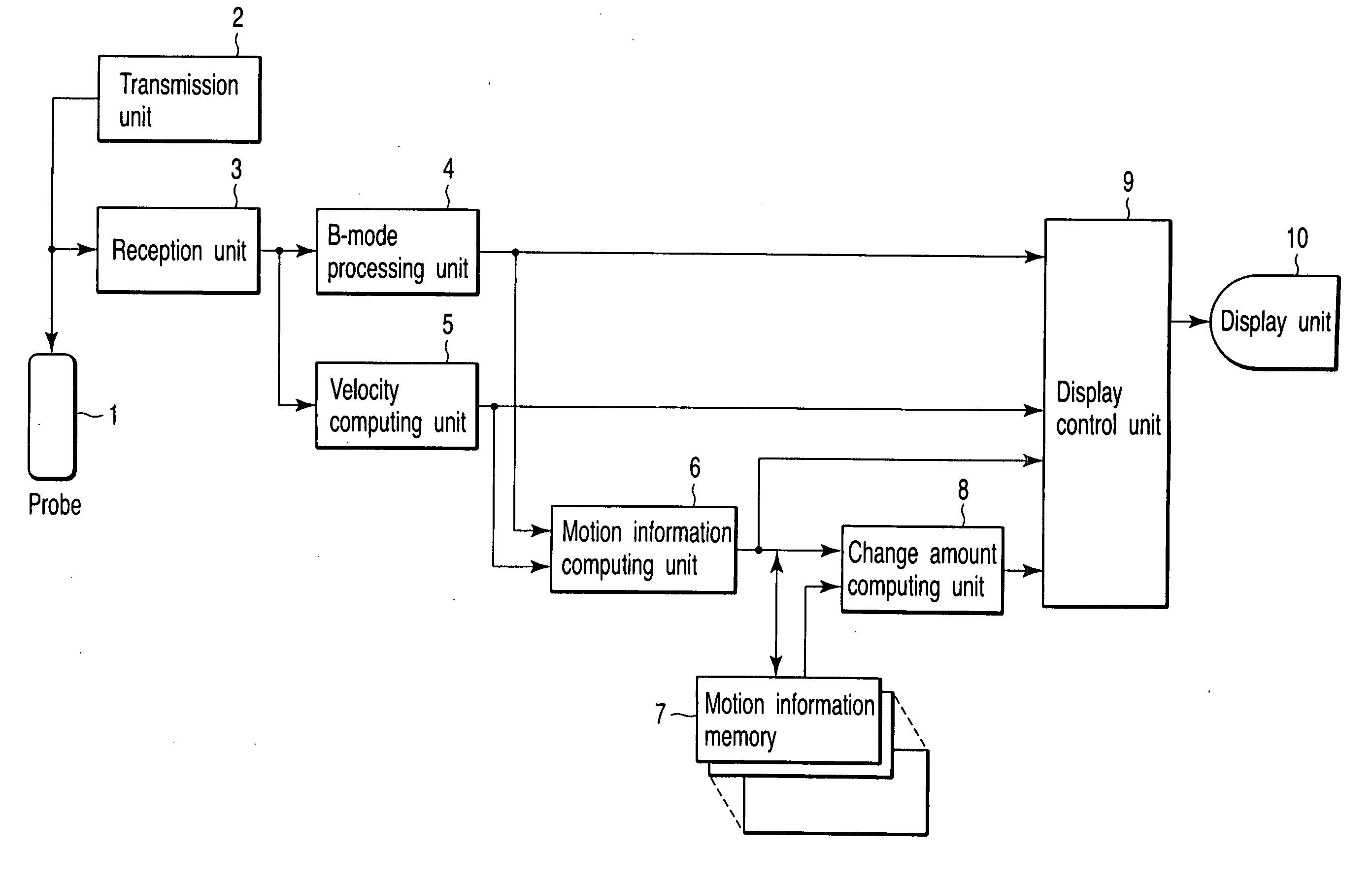
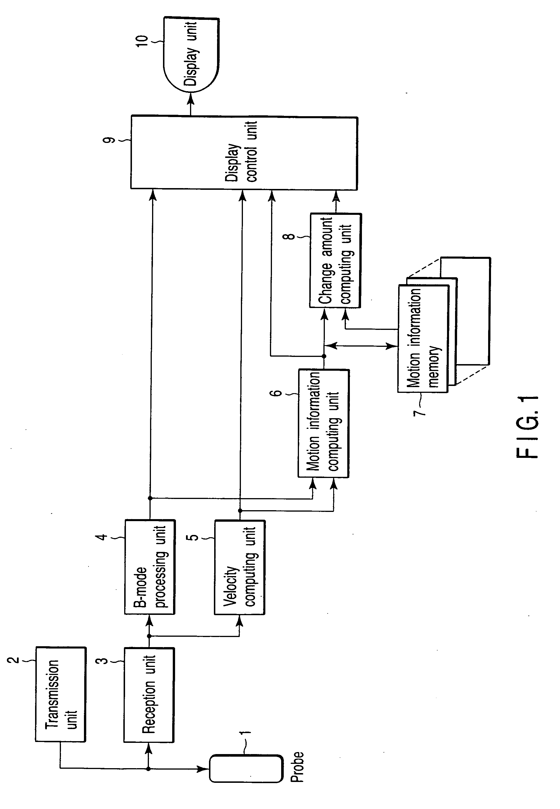
[0033]FIG. 1 is a block diagram showing the arrangement of an ultrasound diagnostic apparatus according to the first embodiment.

[0034] As shown in FIG. 1, the ultrasound diagnostic apparatus of the first embodiment includes an ultrasound probe 1, transmission unit 2, reception unit 3, B-mode processing unit 4, velocity computing unit 5, motion information computing unit 6, motion information memory 7, change amount computing unit 8, display control unit 9, and display unit 10.

[0035] The ultrasound probe 1 comprises an ultrasound transducer array of a plurality of ultrasound transducers which convert electrical signals into ultrasound waves. The ultrasound probe 1 transmits / receives ultrasound waves by using the ultrasound transducer array. Assume that the ultrasound probe 1 in the first embodiment is a sector probe designed for cardiac examination.

[0036] The transmission unit 2 generates a driving signal with a predetermined delay characteristic for each ultrasound transducer so ...

second embodiment

[0060] In the first embodiment described above, a comparison parameter is calculated by comparing two motion information images respectively obtained in different phases for each pixel. Owing to various state changes such as changes in slice (scan position in each phase) before and after the application of load, respiration, and heart rate, there is, however, no guarantee that the positional relationship between two motion information images as comparison targets will remain the same. A shift in the positional relationship between two motion information images may degrade the stability of a comparison parameter.

[0061] The second embodiment directed to avoid the above inconvenience will be described below.

[0062]FIG. 4 is a block diagram showing the arrangement of an ultrasound diagnostic apparatus according to the second embodiment. Note that the same reference numerals as in FIG. 1 denote the same parts in FIG. 4, and a detailed description thereof will be omitted.

[0063] As shown...

third embodiment

[0079] The third embodiment directed to avoid a deterioration in the stability of comparison parameters due to a shift in the positional relationship between two motion information images will be described.

[0080]FIG. 8 is a block diagram showing the arrangement of an ultrasound diagnostic apparatus according to the third embodiment. Note that the same reference numerals as in FIG. 1 denote the same parts in FIG. 8, and a detailed description thereof will be omitted.

[0081] As shown in FIG. 8, the ultrasound diagnostic apparatus of the third embodiment includes an ultrasound probe 1, transmission unit 2, reception unit 3, B-mode processing unit 4, velocity computing unit 5, motion information computing unit 6, motion information memory 7, display unit 10, change amount computing unit 13, and display control unit 14. That is, the ultrasound diagnostic apparatus of the third embodiment comprises the change amount computing unit 13 and display control unit 14 in place of the change amo...


PUM


Abstract

An ultrasound diagnostic apparatus which performs diagnosis of a subject to be examined by using an ultrasound probe which emits ultrasound waves and receives the ultrasound waves reflected by the subject, includes a measuring section which measures a motion velocity of local tissue of the subject by using an ultrasound waves transmitted/received by the ultrasound probe, an acquiring section which acquires motion information representing a strain or displacement of the tissue on the basis of the motion velocity, and a calculating section which calculates a parameter value representing a change amount of motion of the tissue with a change in load on the basis of two pieces of motion information acquired by the acquiring section in two load states in which different loads are applied to the subject.

Description

CROSS-REFERENCE TO RELATED APPLICATIONS [0001] This application is based upon and claims the benefit of priority from prior Japanese Patent Application No. 2004-210110, filed Jul. 16, 2004, the entire contents of which are incorporated herein by reference. BACKGROUND OF THE INVENTION [0002] 1. Field of the Invention [0003] The present invention relates to an ultrasound diagnostic apparatus and ultrasound image processing method which estimate the speed of living tissue such as cardiac muscle by using ultrasound waves, and output the local motion information of the tissue by processing the estimated velocity information, thereby providing information effective for medical diagnosis. [0004] 2. Description of the Related Art [0005] With regard to living tissue such as cardiac muscle, it is very important for the diagnosis of the tissue to objectively and quantitatively evaluate its function. [0006] Various kinds of quantitative evaluation methods have been tried. A stress echo method u...

Claims


Application Information

Patent Timeline
Patent Type & Authority Applications(United States)
IPC IPC(8): A61B8/14
CPCA61B5/0048A61B8/08A61B8/0883A61B8/13A61B8/14A61B8/485G01S7/52087G01S15/8979A61B8/461
Inventor ABE, YASUHIKO
Owner TOSHIBA MEDICAL SYST CORP
Why Eureka
Try Eureka