Fuel fired hydrogen generator

Active Publication Date: 2006-02-23
POWERTAP HYDROGEN FUELING CORP
View PDF77 Cites 31 Cited by
  • Summary
  • Abstract
  • Description
  • Claims
  • Application Information

AI Technical Summary

Benefits of technology

[0005] As an alternative to the hydrogen-storage schemes discussed above, a compressor, single stage or multistages, may be driven by an ordinary internal combustion (IC) engine, which may run at an efficiency of 31% (engine efficiency=engine power output/LHV of

Problems solved by technology

The modifications to present practice to achieve the improved process are relatively straightforwar

Method used


Image

  • Fuel fired hydrogen generator
  • Fuel fired hydrogen generator

Examples


Embodiment Construction

[0033] A description of preferred embodiments of the invention follows.

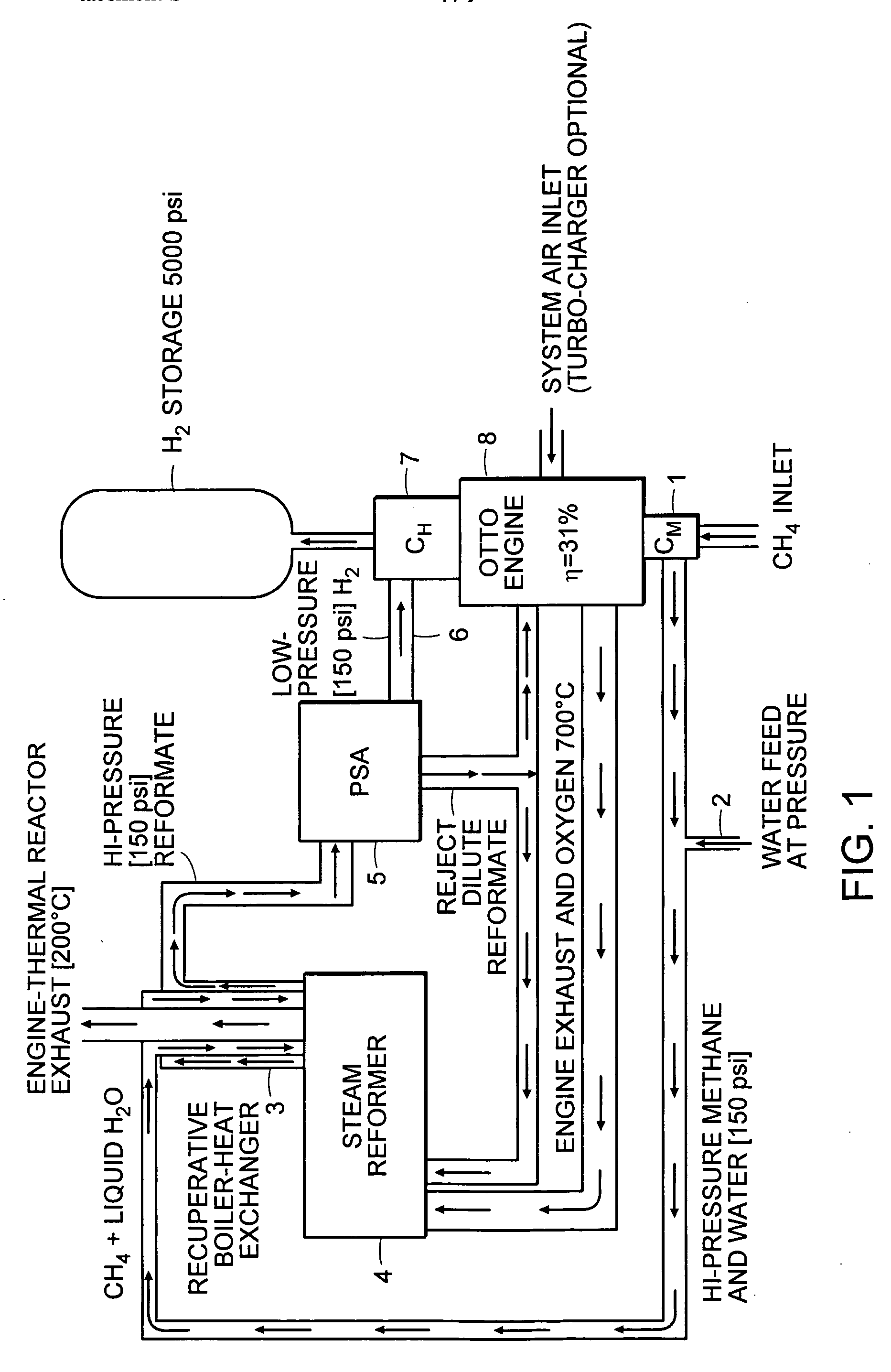
[0034] Referring to the schematics illustration of FIG. 1, it will be more clearly understood how the combination of hydrogen generation, hydrogen separation, lean burn Otto combustion cycle, and hydrogen compression and storage synergistically work together in a system of the invention. The following example contains specific amounts of inputs and values of variables (temperature, pressure, etc) in order to provide an example of the efficiency improvement and energy cost saving possible with the present invention. These specific examples are not to be taken as limiting the scope of the invention.

[0035] As shown in FIG. 1, the system includes a natural gas (methane) compressor (CM) 1, which is driven by an Otto engine 8. Natural gas is the only system energy input in this embodiment. (Note that while natural gas is presently the preferred embodiment, the system can utilize fuels other than natural gas, includin...


PUM


Abstract

A system for making and storing hydrogen comprises an IC engine, a thermal reactor to convert hydrocarbon fuels to reformate, and a separation means to separate the reformate into a hydrogen stream and a hydrogen depleted reformate stream. The hydrogen stream is compressed and stored. The hydrogen depleted reformate stream is split and sent to a thermal reactor and the IC engine. The IC engine drives the compressor for hydrogen as well as the compressor for the fuel inlet to the system. The described system and process achieves high efficiency in fuel conversion and hydrogen storage.

Description

RELATED APPLICATION [0001] This application claims the benefit of U.S. Provisional Application No. 60 / 579,097, filed on Jun. 11, 2004, the entire teachings of which are incorporated herein by reference.BACKGROUND OF THE INVENTION [0002] The field of invention pertains to a system that combines an IC engine with a fuel processor to achieve a system that consumes hydrocarbon fuels and generates and stores hydrogen with high efficiency and low operation cost. [0003] Hydrogen as a fuel has attracted increasing attention. The advantages of hydrogen fuel include: a) fuel cells, using hydrogen as fuel, can achieve thermal efficiency higher than 60% (thermal efficiency=electric energy output / thermal energy input); b) hydrogen fuel is considered zero-emission fuel since the consumption of hydrogen only yields water. However, storage and distribution of hydrogen on a large scale is capital and energy intensive, which hinders the widespread use of hydrogen fuel in the economy. Currently, the m...

Claims


Application Information

Patent Timeline
IPC IPC(8): H01M8/06
CPCC01B3/34H01M8/0668C01B3/56C01B2203/0233C01B2203/0405C01B2203/043C01B2203/047C01B2203/0475C01B2203/0495C01B2203/066C01B2203/0811C01B2203/0822C01B2203/0827C01B2203/0866C01B2203/1241C01B2203/1294H01M8/04201H01M8/0618C01B3/503Y10S123/12Y02P20/10Y02P30/00Y02E60/50
Inventor CLAWSON, LAWRENCE G.
Owner POWERTAP HYDROGEN FUELING CORP
Why Eureka
Try Eureka