Capacitance type physical quantity detector

a technology of capacitive type and detector, applied in the direction of resistance/reactance/impedence, instruments, mechanical means, etc., can solve the problems of increasing the chip area boosting up the cost,

Inactive Publication Date: 2006-02-23
DENSO CORP +1
View PDF6 Cites 35 Cited by
  • Summary
  • Abstract
  • Description
  • Claims
  • Application Information

AI Technical Summary

Benefits of technology

[0023] As represented by the formula (1), the drive voltage V has a relation (V=a / ΔC (a: constant)) which is reversely proportional to the temperature characteristics of the sensor unit, i.e., reversely proportional to the temperature characteristics ΔC. Therefore, unlike the feedback capacitance Cf and the reference voltage Vr, the temperature characteristics of the drive voltage V describe a curve. However, the circuit constitution becomes complex if the correction is effected relying on a curve. In the present detector, therefore, a plurality of variable resistors having different temperature coefficients are changed over, and a curve of desired temperature characteristics is approximated by straight lines. This makes it possible to correct the temperature characteristics of the sensor unit relying upon the drive voltage V despite of a simple constitution.

Problems solved by technology

To form the adjusting voltage having temperature characteristics, however, it is necessary to separately provide a correction circuit portion of a complex circuit constitution, causing an increase in the chip areas and boosting up the cost.
It is also possible to correct the temperature characteristics relying upon a complex digital signal processing, boosting, however, the cost, too.

Method used


Image

  • Capacitance type physical quantity detector
  • Capacitance type physical quantity detector
  • Capacitance type physical quantity detector

Examples


first embodiment

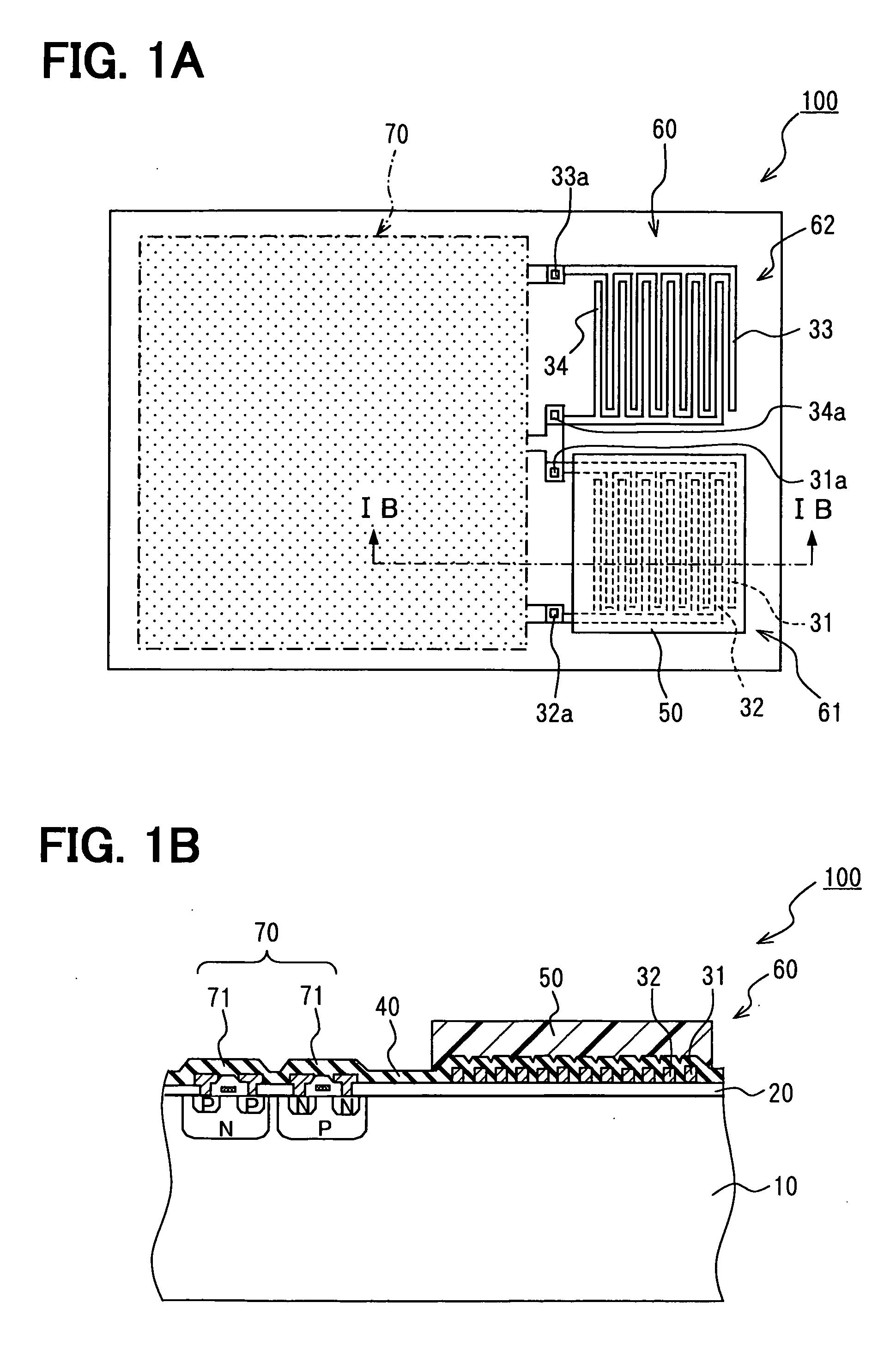
[0036]FIG. 1 is a view schematically illustrating the constitution of a capacitance type humidity sensor according to this embodiment, wherein FIG. 1A is a plan view and FIG. 1B is a sectional view along the section IB-IB in FIG. 1A. In FIG. 1A illustrating the sensor unit, the electrodes and wiring are partly illustrated in a see-through manner, and the circuit portion is omitted.

[0037] In FIG. 1B, reference numeral 10 denotes a semiconductor substrate which in this embodiment is made of silicon. A silicon oxide film 20 is formed as an insulating film on the upper surface of the semiconductor substrate 10. Further, a pair of detecting electrodes 31 and 32 are arranged on the same plane on the silicon oxide film 20 facing each other and being spaced apart.

[0038] There is no particular limitation on the shape of the detecting electrodes 31 and 32. In this embodiment, however, the detecting electrodes 31 and 32 are formed in the shape of comb teeth as shown in FIG. 1A. Employment of...

second embodiment

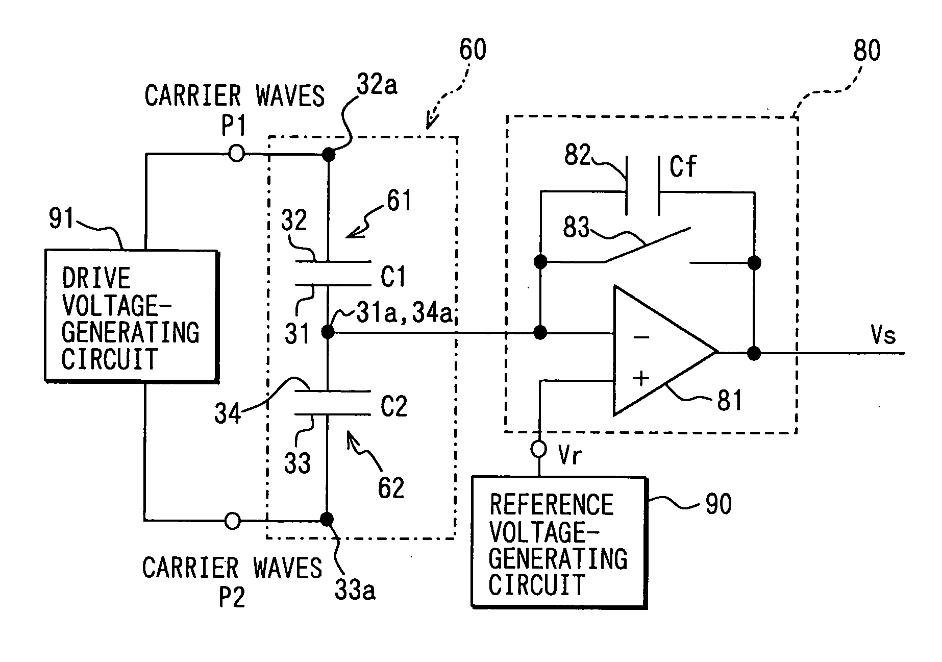
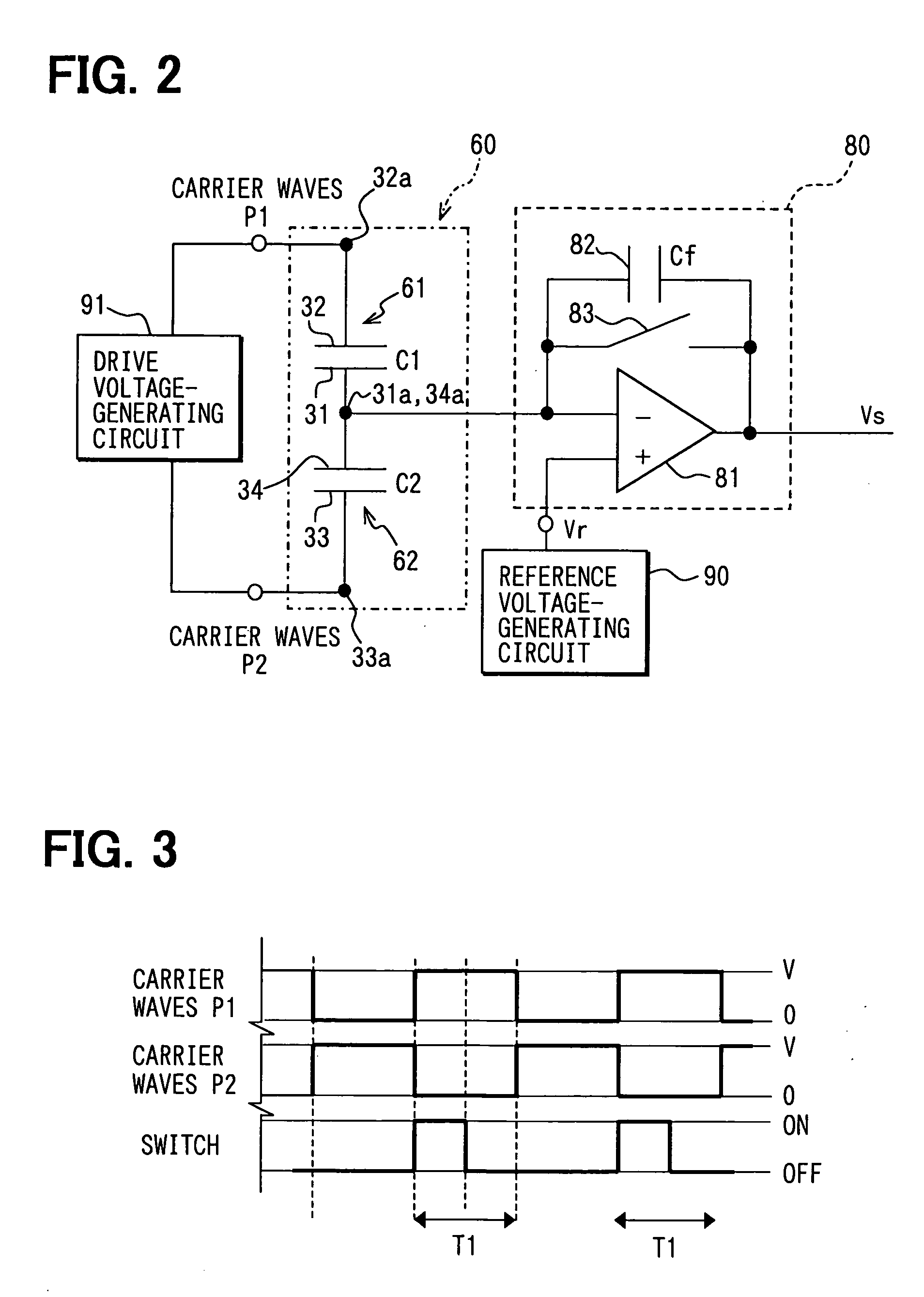
[0062] Next, a second embodiment will be described with reference to FIGS. 8 and 9. FIG. 8 is a diagram illustrating the temperature characteristics of the reference voltage for correcting the temperature characteristics of the sensor unit 60 shown in FIG. 4, and FIG. 9 is a diagram illustrating the constitution of the reference voltage-generating circuit 90 for imparting predetermined temperature characteristics to the reference voltage Vr.

[0063] The capacitance type humidity sensor 100 of the second embodiment is largely common to that of the first embodiment. Therefore, common portions are not described in detail but different portions are described in detail.

[0064] The second embodiment is different from the first embodiment with respect to that the temperature characteristics of the sensor unit 60 are corrected by the reference voltage Vr.

[0065] In this embodiment, the temperature characteristics of the sensor unit 60 are corrected by the reference voltage Vr applied to the ...

third embodiment

[0069] Next, a third embodiment will be described with reference to sectional views of FIGS. 10 and 11 illustrating the capacitance type humidity sensor 10. FIG. 10 is a diagram illustrating the temperature characteristics of the drive voltage for correcting the temperature characteristics of the sensor unit 60 shown in FIG. 4, and FIG. 11 is a diagram illustrating the constitution of a drive voltage-generating circuit 91 for imparting predetermined temperature characteristics to the drive voltage V.

[0070] The capacitance type humidity sensor 100 of the third embodiment is largely common to that of the first embodiment. Therefore, common portions are not described in detail but different portions are described in detail.

[0071] The third embodiment is different from the first embodiment with respect to that the temperature characteristics of the sensor unit 60 are corrected by the drive voltage V.

[0072] In this embodiment, the temperature characteristics of the sensor unit 60 are ...


PUM

PropertyMeasurementUnit
RHaaaaaaaaaa
temperatureaaaaaaaaaa
capacitanceaaaaaaaaaa

Abstract

A capacitance type physical quantity detector includes a sensor unit of which the capacitance varies depending upon a change in the physical quantity and a C-V converter unit which converts a change in the capacitance of said sensor unit into a voltage. The C-V converter unit includes an operational amplifier, a feedback capacitor, switching means connected in parallel with said feedback capacitor, a reference voltage-generating circuit for applying a reference voltage to the operational amplifier, and a drive voltage-generating circuit for applying a drive voltage to said sensor unit. At least any one of the feedback capacitance of said feedback capacitor, the reference voltage formed by said reference voltage-generating circuit or the drive voltage formed by said drive voltage-generating circuit varies depending upon the temperature to correct temperature characteristics of the sensor unit.

Description

CROSS REFERENCE TO RELATED APPLICATION [0001] This application is based upon, claims the benefit of priority of, and incorporates by reference the contents of, Japanese Patent Application No. 2004-238727 filed on Aug. 18, 2004. FIELD OF THE INVENTION [0002] The present invention relates to a capacitance type physical quantity detector for detecting physical quantities such as humidity and the like. BACKGROUND OF THE INVENTION [0003] The present applicant has previously proposed in JP-A-2002-243690 a capacitance type humidity sensor having a moisture-sensitive film of which the specific inductivity varies depending upon the humidity interposed between a pair of electrodes. [0004] The above capacitance type humidity sensor has a sensor unit which comprises a pair of electrodes formed like comb teeth on the same plane of a substrate, and a moisture-sensitive film formed so as to cover the pair of electrodes. Further, in order to detect fine variations in the capacitance maintaining goo...

Claims


Application Information

Patent Timeline
Patent Type & Authority Applications(United States)
IPC IPC(8): G01N19/00
CPCG01D5/24G01D5/2405G01N27/223
Inventor ITAKURA, TOSHIKAZUISOGAI, TOSHIKI
Owner DENSO CORP
Why Eureka
Try Eureka