
Externally serviceable transmission sump fill pipe and drain port assembly

a technology of external serviceable transmission and fill pipe, which is applied in the direction of crankshafts, gearing details, machines/engines, etc., can solve the problems of multiple potential fluid leak paths, differences in the degree of overlap of two torque windows, and the torque applied to one element, so as to achieve the effect of reducing the degree of overlap between the two torque windows

Active Publication Date: 2006-02-23
FORD GLOBAL TECH LLC
View PDF5 Cites 22 Cited by
  • Summary
  • Abstract
  • Description
  • Claims
  • Application Information

AI Technical Summary

Benefits of technology

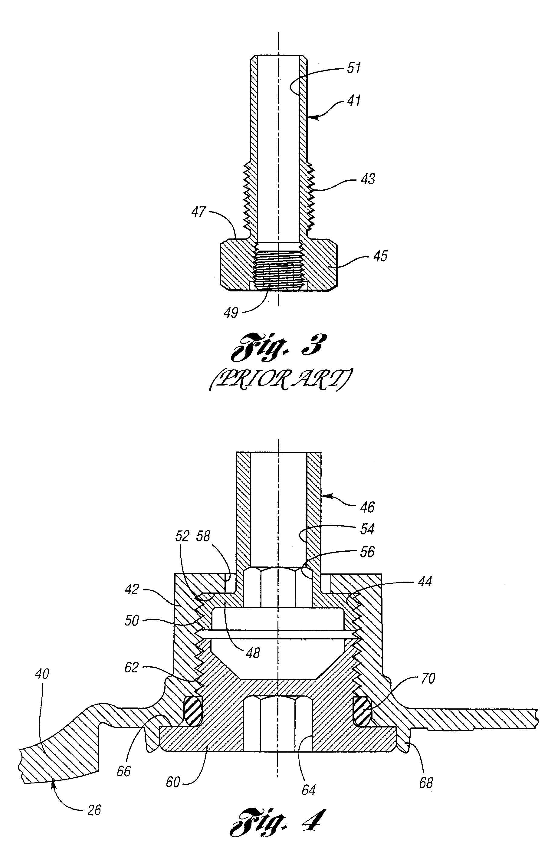
[0009] The invention comprises a fill pipe and drain plug assembly that includes a single sealing interface rather than multiple sealing interfaces typical of known fill pipe and drain plug assemblies. The invention is characterized also by improved corrosion resistance and reduced weight in comparison to known designs.
[0012] When filling of the sump is required, the plug can be removed and transmission fluid can be added to the sump through the fill pipe using a fill adapter that may be threaded into the pan threads rather than into the fill pipe itself. Because of this design of the fill pipe and the drain plug, a conventional externally threaded plug may be used. The fill pipe itself can be removed and reinstalled from outside the transmission without requiring removal of the pan.
[0013] In addition to overcoming the leakage problem associated with multiple sealing interfaces of known designs, the design of the present invention avoids problems associated with torquing and loosening of a concentric plug, a fill pipe and a fill adapter. Each threaded element of the design can be torqued during assembly independently of the torque requirements of other elements of the assembly.

Problems solved by technology

That design may result in multiple potential fluid leak paths at the sealing interface of the fill pipe with the sump and at the interface of the fill pipe and the plug.
A torque applied to one element, therefore, may be inconsistent with the recommended torque for the other element.
Further, any corrosion at either of the threaded connections will cause differences in the degree of overlap of the two torque windows.
Further, known designs of this type have multiple sealing interfaces, each interface creating a potential fluid leak path.

Method used


Image

  • Externally serviceable transmission sump fill pipe and drain port assembly
  • Externally serviceable transmission sump fill pipe and drain port assembly
  • Externally serviceable transmission sump fill pipe and drain port assembly

Examples


Embodiment Construction

)

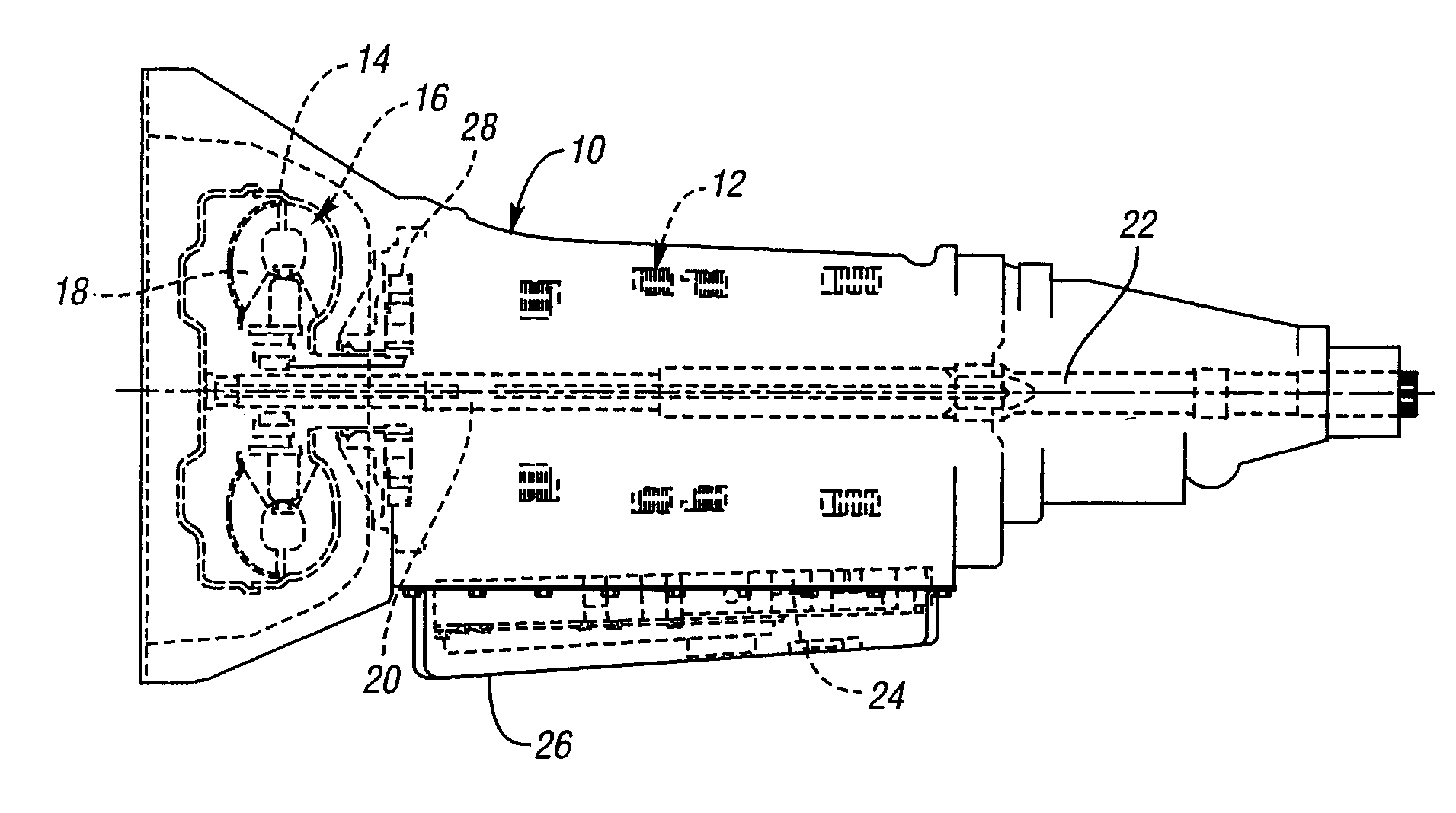
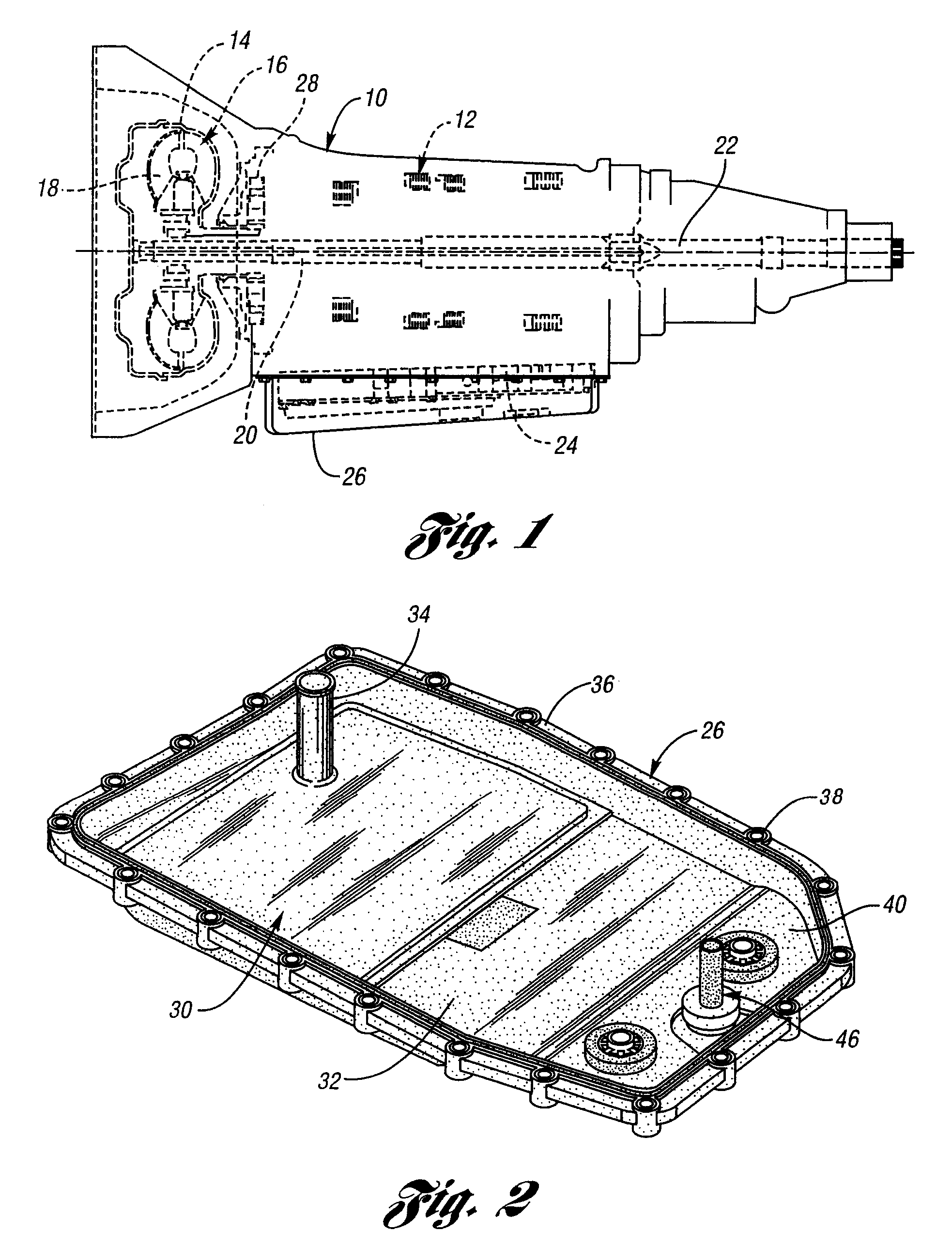
[0018]FIG. 1 shows, in schematic, cross-sectional form, a typical automatic transmission of the kind currently used with rear wheel drive automotive vehicles. FIG. 1 is included in the disclosure to illustrate a structural environment for the transmission fluid fill pipe and drain plug assembly of the invention. Although FIG. 1 illustrates a transmission for a rear wheel drive vehicle, the invention may be used as well in a transmission of a so-called transaxle type, wherein engine torque is delivered to forward traction wheels of the vehicle.

[0019] Numeral 10 in FIG. 1 designates an automatic transmission housing. Enclosed in the housing 10 is a planetary gear system 12, which includes friction clutches and brakes for establishing and disestablishing torque flow paths through planetary gear elements. The friction clutches and brakes are actuated by fluid pressure operated actuators in known fashion.

[0020] Engine torque is delivered to the impeller 14 of a hydrokinetic torque con...


PUM


Abstract

A transmission fluid sump for an automotive transmission comprising a reservoir portion, a threaded extension on the reservoir portion and a fill pipe threadably connected to the extension. A closure member seals a central opening in the extension independently of the fill pipe, thereby avoiding overlapping torque windows for the fill pipe and the closure member while providing a single leak flow path for the transmission fluid.

Description

BACKGROUND OF INVENTION [0001] 1. Field of the Invention [0002] The invention relates to an oil reservoir or sump for an automatic transmission mechanism in an automotive vehicle powertrain. [0003] 2. Background Art [0004] An automatic power transmission mechanism in a contemporary automotive vehicle powertrain includes a gear system, typically a planetary gear system with multiple gear ratios, fluid pressure actuated friction clutches and brakes to establish and disestablish torque flow paths through the gearing, and a hydrokinetic torque converter including an impeller connected to the crankshaft of an internal combustion engine and a turbine connected drivably to the torque input element of the gear system. A positive displacement transmission pump in a transmission housing has a pump driving element connected to the impeller. When the engine is operating, the pump establishes control pressure for fluid pressure actuators for the friction clutches and brakes as well as lubricatio...

Claims


Application Information

Patent Timeline
Patent Type & Authority Applications(United States)
IPC IPC(8): F16H57/02
CPCF16H57/0408Y10T74/2186F16H57/0484F16H57/0452
Inventor HOLUB, PATRICK
Owner FORD GLOBAL TECH LLC
Learn More