Electric arc welder

a technology of electric arc welding and welder, which is applied in the direction of arc welding apparatus, welding apparatus, manufacturing tools, etc., can solve the problems of large switches, large switches, and prone to certain inconsistencies in welding systems,

Active Publication Date: 2006-02-23
LINCOLN GLOBAL INC
View PDF7 Cites 42 Cited by
  • Summary
  • Abstract
  • Description
  • Claims
  • Application Information

AI Technical Summary

Benefits of technology

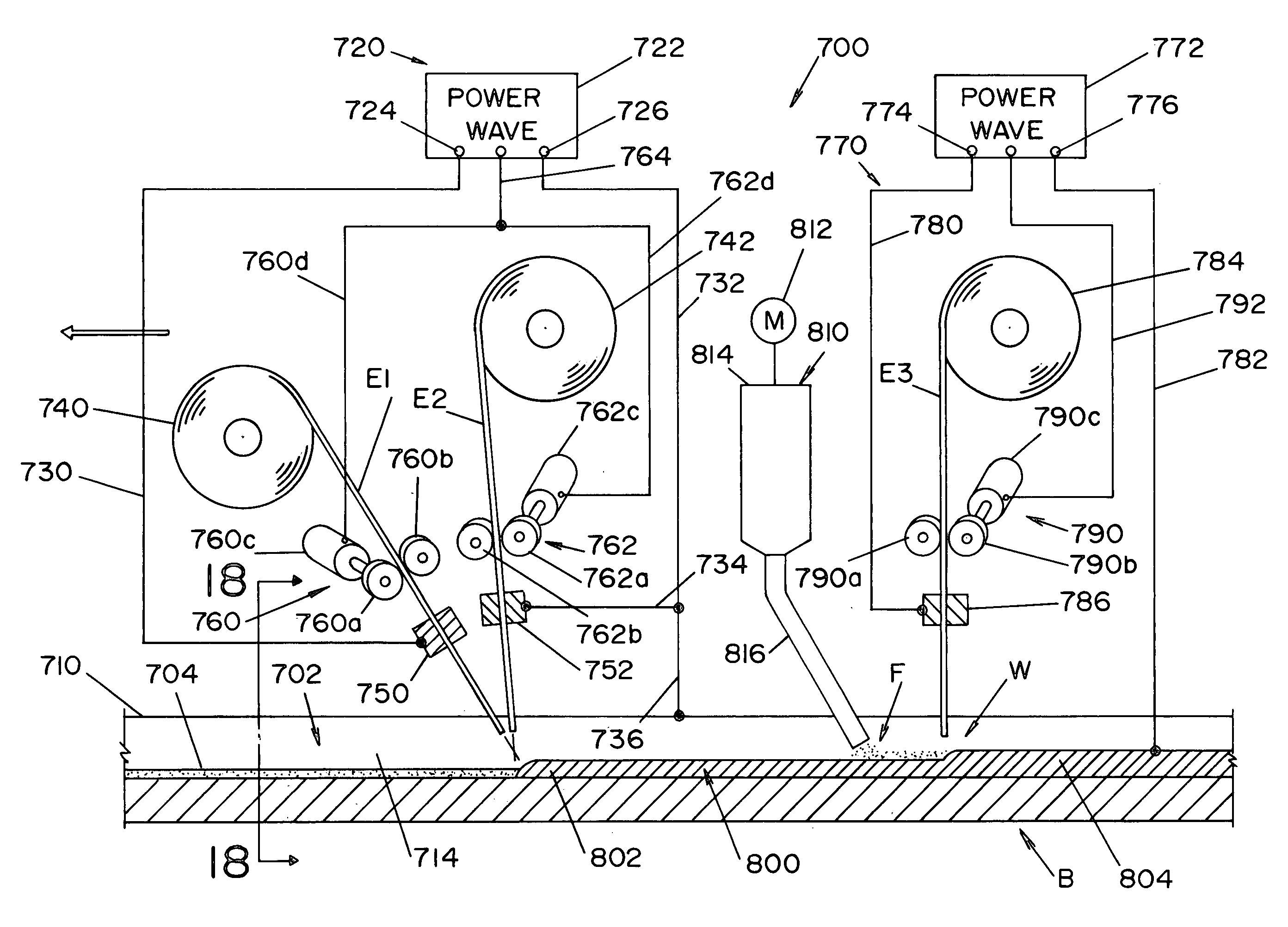
[0017] By using the present invention, the waveform generator for the main power source is provided with a circuit to adjust the frequency of the AC waveform between the series connected lead electrodes. In this manner, the frequency of the AC waveform used in the series connected electrodes is not dictated in any fashion by the frequency of line voltage to the main power source. By adjusting the frequency of the waveform, the welding operation for the series connected electrodes can be modulated to accommodate different diameter electrodes, electrodes with different material and a variety of currents to customize the welding operation in a manner not available in the prior art. Furthermore, the waveform generator of the present invention has a circuit for adjusting duty cycles of the AC waveforms from the main power source. Thus, the welding operation can be adjusted between penetration and deposition to customize the operation of the weld process. To accomplish this objective, the magnitude of the positive current portion of the waveform are controlled independently or as a percentage of the magnitude of the negative portion of the AC waveform. All of these adjustment circuits allow the main power source to be adjusted in frequency, duty cycle and / or amplitudes to customize the welder for providing an optimized welding process, while still employing the tremendously advantageous series connected electrodes.

Problems solved by technology

Such welding systems are quite prone to certain inconsistencies caused by arc disturbances due to magnetic interaction between two adjacent tandem electrodes.
Consequently, such system overcame the disadvantage of requiring special power supplies for each electrode in a tandem welding operation of the type used in pipe welding; but, there is still the disadvantage that the switches must be quite large and the input, paralleled power supplies must be accurately matched by being driven from a single current command signal.
However, the system still required large switches.
In ethernet interconnections, the timing cannot be accurately controlled.
Due to timing limitation, these networks dictated use of tandem electrode systems of the type using only general synchronizing techniques.
Such systems were not suitable for central control by the internet and / or local area network control because an elaborate network to merely provide offset between cells was not advantageous.
This technology, as the normal transformer technology, has experienced difficulty in controlling the dynamics of the weld puddle.
The disadvantage of the series electrode concept was that there was very little penetration.
This limited the relationship of the two motors driving the wire feeders.
Thus, using the prior art system was restricted.
Since there is a limited application of this technology, it was not possible to sell series connected tandem electrode equipment for general purpose electric arc welding.

Method used


Image

  • Electric arc welder
  • Electric arc welder
  • Electric arc welder

Examples


Embodiment Construction

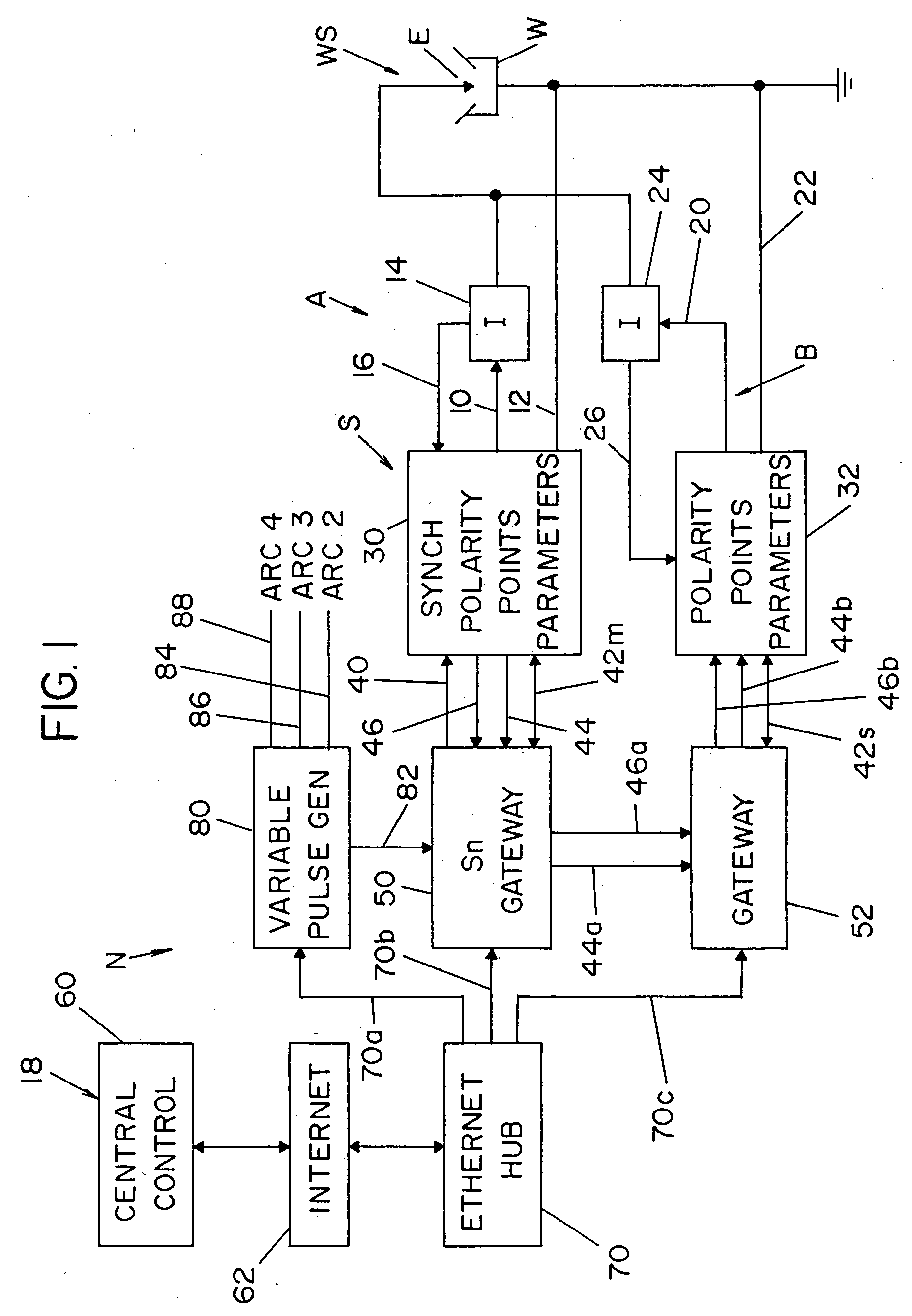
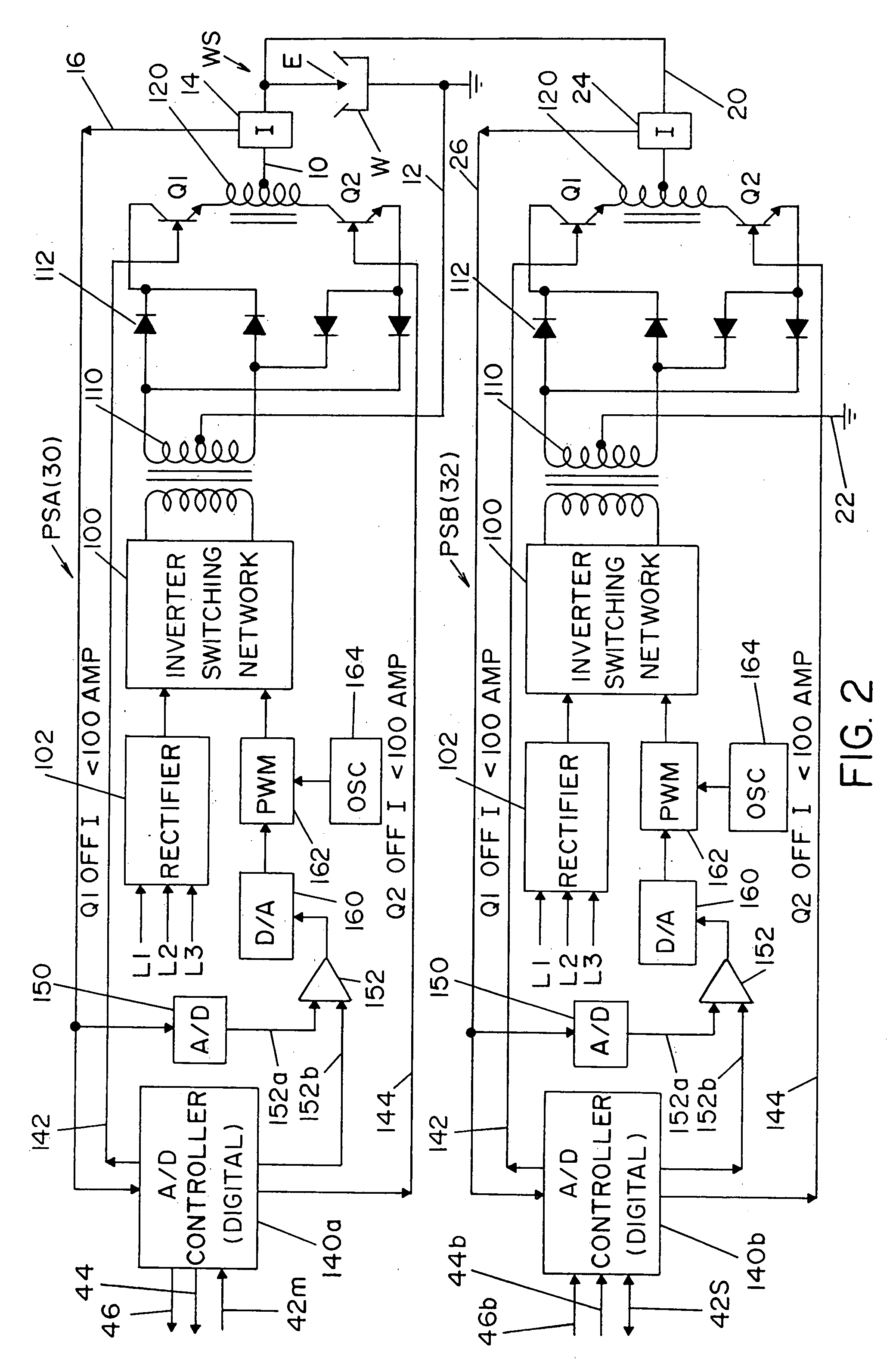
[0042] Referring now to the drawings wherein the showings are for the purpose of illustrating a preferred embodiment of the invention only and not for the purpose of limiting same, the system used in practicing the invention is shown in detail in FIGS. 1, 2 AND 16. In FIG. 1 there is a single electric arc welding system S in the form of a single cell to create an alternating current as an arc at weld station WS. This system or cell includes a first master welder A with output leads 10, 12 in series with electrode E and workpiece W in the form of a pipe seam joint or other welding operation. Hall effect current transducer 14 provides a voltage in line 16 proportional to the current of welder A. Less time critical data, such as welding parameters, are generated at a remote central control 18. In a like manner, a slave following welder B includes leads 20, 22 connected in parallel with leads 10, 12 to direct an additional AC current to the weld station WS. Hall effect current transduce...


PUM

PropertyMeasurementUnit
currentaaaaaaaaaa
frequencyaaaaaaaaaa
timeaaaaaaaaaa

Abstract

An electric arc welder for depositing weld metal along a groove between two edges of a metal workpiece where the welder comprises a first electrode driven by a first wire feeder toward a point in said groove, a second electrode driven by a second wire feeder toward the point and a main power source with a first output terminal connected to the first electrode and a second output terminal connected both to the second electrode and directly or indirectly to the metal workpiece to create a second electrode path and a workpiece path. The power source includes a high speed switching output stage for creating current with a selected AC waveform between the first and second output terminals where the waveform of the main power source is generated by a waveform generator controlling a pulse width modulator circuit to determine the current operation of the output stage.

Description

[0001] The present invention relates to the art of electric arc welding and more particularly to an electric arc welder system to operate tandem electrodes. INCORPORATION BY REFERENCE [0002] The present invention is directed to an electric arc welding system utilizing high capacity alternating circuit power sources for driving two or more tandem electrodes of the type used in seam welding of large metal blanks. Although the invention can be used with any standard AC power supply with switches for changing the output polarity, it is preferred that the power supplies use the switching concept disclosed in Stava U.S. Pat. No. 6,111,216 wherein the power supply is an inverter having two large output polarity switches with the arc current being reduced before the switches reverse the polarity. The power source can be a chopper operated at high switching speeds. Consequently, the term “switching point” is a complex procedure whereby the power supply is first turned off awaiting a current ...

Claims


Application Information

Patent Timeline
Patent Type & Authority Applications(United States)
IPC IPC(8): B23K9/09
CPCB23K9/093B23K9/0953B23K9/188B23K9/1068B23K9/1075B23K9/1062
Inventor MYERS, RUSSELL K.O'DONNELL, TIMOTHY M.YOST, ALONZO P. O.
Owner LINCOLN GLOBAL INC
Why Eureka
Try Eureka