Deformable mirror method including bimorph flexures

a deformation mirror and bimorph technology, applied in the field of long stroke mems deformation mirror arrays, can solve the problems of limited stroke of available dms, widespread adoption of ao, and high cos

Inactive Publication Date: 2006-02-23
HELMBRECHT MICHEAL ALBERT
View PDF18 Cites 32 Cited by
  • Summary
  • Abstract
  • Description
  • Claims
  • Application Information

AI Technical Summary

Benefits of technology

[0021] It is therefore an object of the present invention to provide improved methods and structures for elevating a platform above a substrate and for precisely controlling the tip, tilt and piston motion of that platform.
[0022] A further object of the invention is to provide a high-degree-of-freedom DM which can be used to compensate for large optical wavefront aberrations, without the need for temperature control or monitoring.

Problems solved by technology

Despite the advantages outlined above, AO has not been universally adopted, even in the aforementioned applications.
Two important factors that have impeded the widespread adoption of AO are the high cost and limited stroke of available DMs.
The continuous surface also means that the deformation produced by each actuator is not tightly confined to the area of the mirror directly connected to it, but instead may extend across the whole mirror aperture, making precise control of the overall mirror deformation problematic.
This large size precludes their deployment in many optical systems that might otherwise benefit from AO.
Their fabrication methods also make these DMs expensive to manufacture and do not permit easy integration of control electronics into the DM structure.

Method used


Image

  • Deformable mirror method including bimorph flexures
  • Deformable mirror method including bimorph flexures
  • Deformable mirror method including bimorph flexures

Examples


first embodiment

[0052] The following is a general overview of the process of the current invention for fabricating the DM. The process involves separately fabricating the MEMS structure and the addressing and sensing circuits on two separate wafers, then assembling them together as shown in FIGS. 4A and 4B. FIG. 4A is a process flow diagram and FIG. 4B illustrates the corresponding structure at each step. As shown at step 400, each mirror segment 380 is fabricated by reactive ion etching (RIE) the top single crystal silicon “device” region of a bonded silicon-on-insulator wafer (BSOI). At step 405, the wafer is then coated with a sacrificial layer to fill the trenches left by the previous etch, provide a temporary support for various mechanical structures of the DM, and optionally to act as a dopant source for undoped polysilicon regions. This sacrificial layer might typically be phosphorus-doped silicate glass deposited by low pressure chemical vapor deposition (LPCVD). Alternatively, in cases whe...

third embodiment

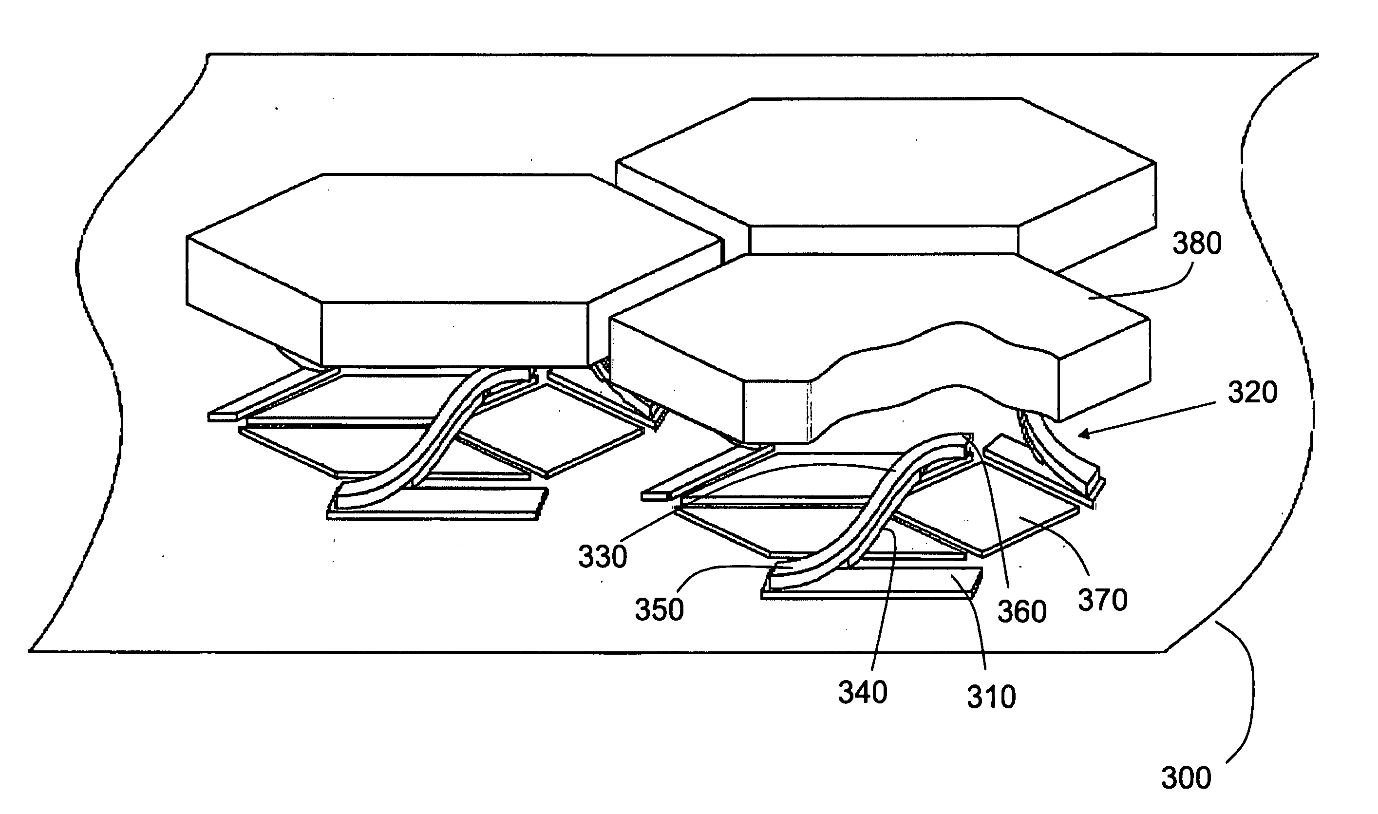
[0070] the DM comprises a substrate 900, which may be a silicon wafer. On top of the substrate 900 are formed a number of control electrodes 960 that are electrically isolated from one another and electrically connected to conductive traces (not shown in FIG. 9) that may either be embedded in the substrate 900 or attached to the surface of the substrate 900. These traces electrically connect the control electrodes 960 directly to bond pads (not shown in FIG. 9) that may be disposed around the perimeter of the DM chip. The control electrodes 960 are arranged in groups of three and are rhombic in shape, so that the footprint of each group is essentially hexagonal.

[0071] Disposed around each group of three control electrodes 960, are three conductive ground pads 910, fabricated from the same material as the control electrodes 960. The ground pads 910 are electrically isolated from the control electrodes 960 and electrically connected to a ground plane embedded in the substrate 900. Att...


PUM


Abstract

An apparatus comprising a substrate; and a platform elevated above the substrate and supported by curved flexures. The curvature of said flexures results substantially from variations in intrinsic residual stress within said flexures. In one embodiment the apparatus is a deformable mirror exhibiting low temperature-dependence, high stroke, high control resolution, large number of degrees of freedom, reduced pin count and small form-factor. Structures and methods of fabrication are disclosed that allow the elevation of mirror segments to remain substantially constant over a wide operating temperature range. Methods are also disclosed for integrating movable mirror segments with control and sense electronics to a produce small-form-factor deformable mirror.

Description

CROSS-REFERENCE TO RELATED APPLICATIONS [0001] This application claims the benefit of U.S. Provisional Patent Application No. 60 / 425,049 entitled Reduced Rotation MEMS Deformable Mirror Apparatus and Method, and U.S. Provisional Patent Application No. 60 / 425,051 entitled Deformable Mirror Method and Apparatus Including Bimorph Flexures and Integrated Drive, both filed Nov. 8, 2003.BACKGROUND OF THE INVENTION [0002] 1. Field of the Invention [0003] This invention relates to a methods and structures for elevating a platform above a substrate and for producing a controlled motion of that platform. It also relates to MEMS deformable mirror (“DM”) arrays, and more particularly to long-stroke MEMS deformable mirror arrays for adaptive optics applications. [0004] 2. Description of the Related Art [0005] Adaptive optics (“AO”) refers to optical systems that adapt to compensate for disadvantageous optical effects introduced by a medium between an object and an image formed of that object. Ho...

Claims


Application Information

Patent Timeline
Patent Type & Authority Applications(United States)
IPC IPC(8): H02N1/00A47B91/00G02B26/06G02B26/08
CPCG02B26/0825G02B26/06
Inventor HELMBRECHT, MICHEAL ALBERT
Owner HELMBRECHT MICHEAL ALBERT
Why Eureka
Try Eureka