Dynamoelectric machine having heat pipes embedded in stator core

a technology of stator core and cooling pipe, which is applied in the direction of magnetic circuits characterised by magnetic materials, magnetic circuit shape/form/construction, magnetic circuit rotating parts, etc., can solve the problems of high torque of electric traction systems, inability to shape cooling paths, and inability to control the direction of cooling paths

Inactive Publication Date: 2006-02-23
BLUWAV SYST LLC
View PDF99 Cites 42 Cited by
  • Summary
  • Abstract
  • Description
  • Claims
  • Application Information

AI Technical Summary

Benefits of technology

[0010] The present invention fulfills the above described needs, at least in part, by providing a method of thermal management of an electric machine having a stator formed, at least in part, of a plurality of soft magnetic composite (SMC) core segments distributed circumferentially about an axis of rotation. A stator core segment configuration is selected in accordance with at least one criterion for a specific machine application. The minimum heat dissipation necessary to maintain the temperature of the selected core segment configuration at peak excitation within acceptable limits is determined. A core model having a configuration corresponding to the selected configuration is used to ascertain thermal distribution at peak excitation. Based on the ascertained thermal distribution in the model, a pattern in the selected core segment configuration is established for placement of at least one heat pipe for removing heat from the core. A core segment is th

Problems solved by technology

Electric traction systems demand high torque from low voltage propulsion units.
Classical issues concerning copper, hysteresis and excess eddy current losses tend to dictate the need for new cooling methods.
In machines with laminated stator cores, there is little freedom for shaping cooling paths.
Liquid cooling

Method used


Image

  • Dynamoelectric machine having heat pipes embedded in stator core
  • Dynamoelectric machine having heat pipes embedded in stator core
  • Dynamoelectric machine having heat pipes embedded in stator core

Examples


Embodiment Construction

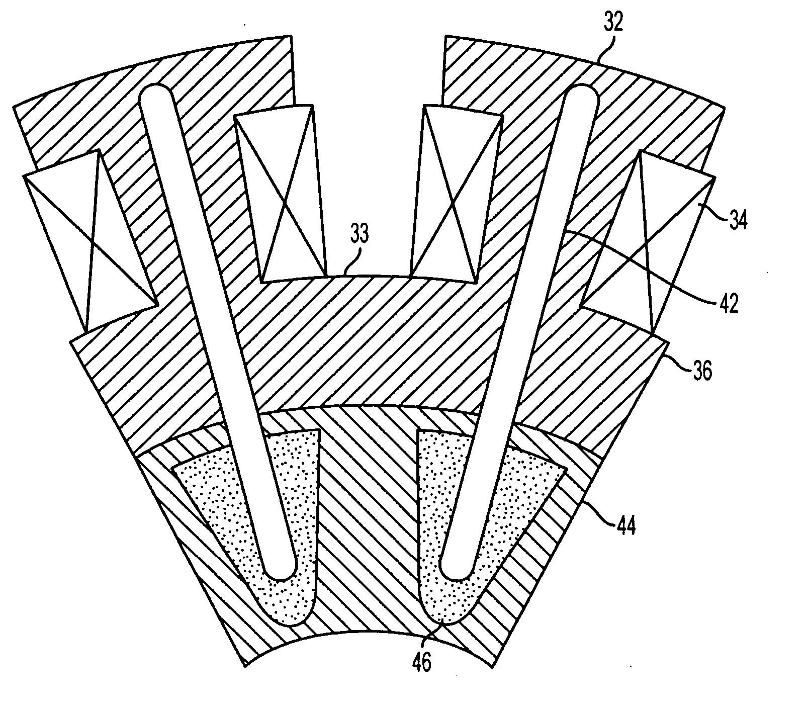
[0021] Computational Fluid Dynamic (CFD) models have confirmed that in a typical magnetic design, a wound magnetic core material can exhibit very high thermal signatures under peak excitation. Depending on the thermal heat capacity and conductivity of the copper or aluminum winding and the core, heat dissipation may be effected by convection and conduction. With the development of SMC technology, heat pipes are used in the present invention for localized cooling of stator cores. Heat pipes advantageously are embedded in SMC material, in contrast to laminated iron cores for which such procedure cannot be effectively realized. The heat pipes can be embedded in the SMC parts in one of two ways; either by shrink-fitting or by bonding them in existing cavities in the SMC cores. In either method, a deep cavity is formed in the bulk of the SMC core. The diameter of the cavity is proportional to the outer diameter of the heat pipe. The length of the cavity does not extend all the way to the...


PUM


Abstract

Thermal management of an electric machine is implemented by selecting a stator core configuration in accordance with an intended machine application and determining the minimum heat dissipation necessary to maintain the temperature of the core segment configuration at peak excitation within acceptable limits is determined. A core model is used to ascertain thermal distribution at peak excitation. In accordance therewith, a pattern in the selected core segment configuration is established for placement of at least one heat pipe for removing heat from the core. Preferably, heat pipes are located at high thermal points in the core segment and oriented in alignment with mapped lines of flux. By placing the heat pipe either at the center of the core or at a recessed boundary layer between the core and winding, the heat pipe can capture and conduct excess heat away from the heat generating areas of the core, thus maintaining the core and the excitation windings at desired temperature.

Description

FIELD OF THE INVENTION [0001] The present invention relates to a cooling system for a dynamoelectric machine and, more particularly, to a machine having cooling pipes embedded in stator core elements. BACKGROUND ART [0002] Development of efficient electric motor drives for vehicles, with improved electronic control systems and portable power sources, has drawn increasing attention as a viable alternative or adjunct to combustion engine drives. For example, U.S. Pat. No. 6,492,756 to Maslov et al. and U.S. Pat. No. 6,617,746 to Maslov et al., both commonly assigned with the present invention, describe motor structures that provide high torque output capability with minimum power consumption, thus especially suitable to electric vehicle propulsion. Electromagnets are used as isolated magnetically permeable structures configured in a stator annular ring. FIG. 1 is a plan view of a motor such as described in the U.S. Pat. No. 6,492,756. Rotor member 20 is an annular ring structure havin...

Claims


Application Information

Patent Timeline
IPC IPC(8): H02K9/00
CPCH02K1/02H02K9/20H02K1/146H02K9/225
Inventor MATIN, KAISERSOGHOMONIAN, ZAREH SALMASI
Owner BLUWAV SYST LLC
Why Eureka
Try Eureka