Series-parallel resonant matching circuit and broadband amplifier thereof

Inactive Publication Date: 2006-02-23
CHUNG-SHAN INSTITUTE OF SCIENCE & TECHNOLOGY; MINISTRY OF NATIONAL DEFENSE
View PDF2 Cites 7 Cited by
  • Summary
  • Abstract
  • Description
  • Claims
  • Application Information

AI Technical Summary

Benefits of technology

[0018] The present invention uses the series-parallel resonant matching circuit for a power amplifier. Accordingl

Problems solved by technology

By the power amplifiers with the design of the narrowband resonant matching circuits, it is difficult to satisfy the requirement of the broadband power amplifier.
The fluctuation of narrowband matching circ

Method used


Image

  • Series-parallel resonant matching circuit and broadband amplifier thereof
  • Series-parallel resonant matching circuit and broadband amplifier thereof
  • Series-parallel resonant matching circuit and broadband amplifier thereof

Examples


Example

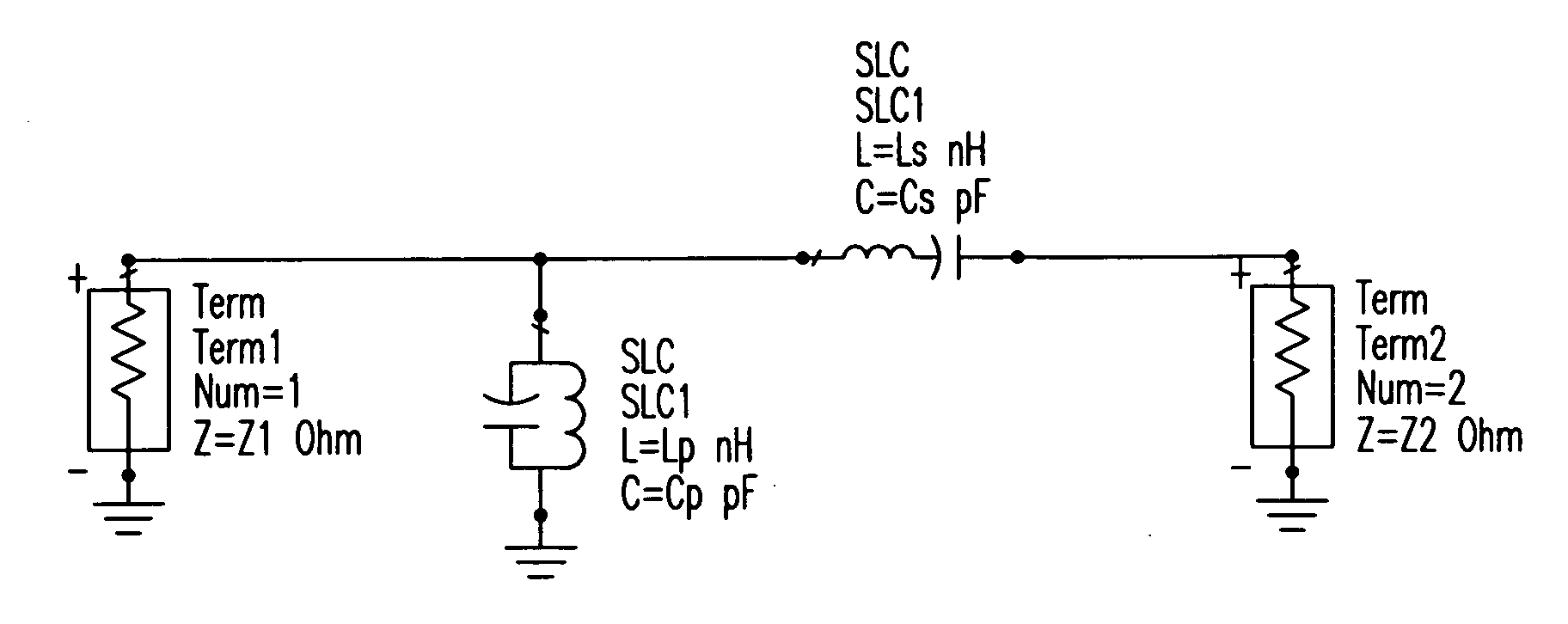
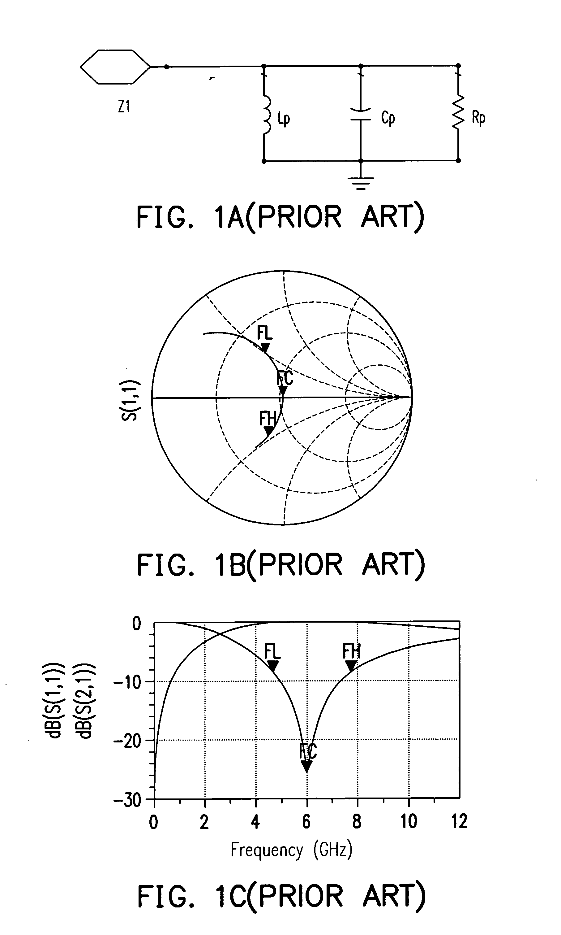
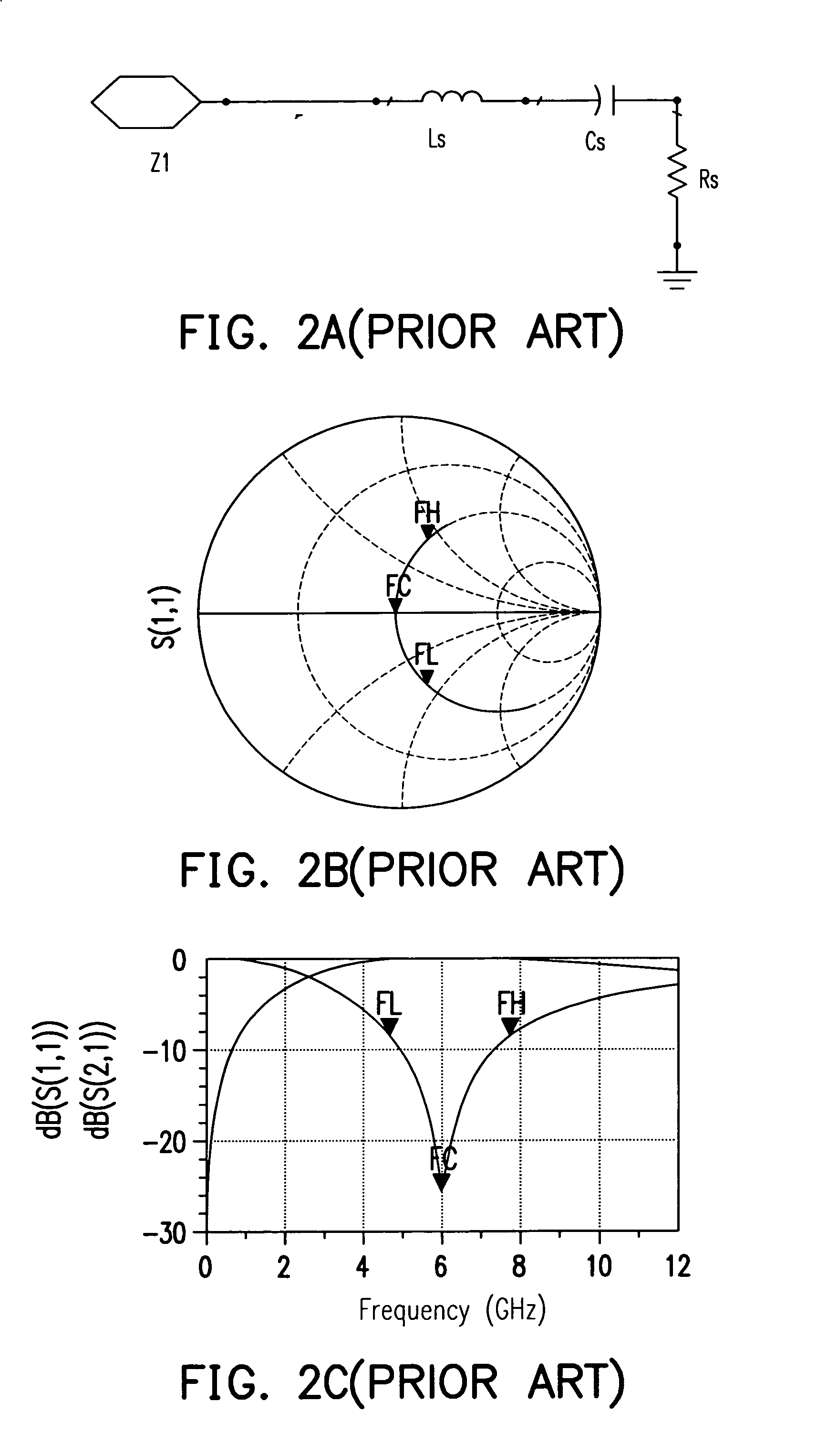
[0036]FIG. 5A is a schematic diagram showing an equivalent circuit of series-parallel resonant matching circuits according to an embodiment of the present invention. In this embodiment, one of ordinary skill in the art will design LP, CP, LS and CS so as to determine bandwidth and create the frequency response. The matching circuit is similar to a two-order band-pass filter. Referring to FIGS. 5B and 5C, when the frequency is lower than the central frequency FC, the impendence is contributed mainly from the capacitor. In contrast, when the frequency is higher than the central frequency FC, the impendence is contributed mainly from the inductor. Accordingly, in the bandwidth from FL to FH, the return loss S11 converges in the circle of the reflection coefficient |Γ| of the Smith chart, wherein S21 represents the insertion loss.

[0037]FIG. 6 is a schematic block diagram showing an N-stage broadband power amplifier according to an embodiment of the present invention. The N-stage broadb...


PUM


Abstract

A series-parallel resonant matching circuits and a broadband power amplifier thereof are disclosed. The series-parallel resonant matching circuit is connected to the last power transistor and the next power transistor. The series-parallel resonant matching circuit comprises a series matching inductor, a parallel matching inductor and an impedance transformation unit. The impedance transformation unit is connected between the series matching inductor and the intrinsic parallel matching inductor for transforming impedance. The parallel matching inductor and the parallel capacitor of a last level power transistor constitute a LC parallel resonant circuit, the series matching inductor and the series intrinsic capacitor of a next level power transistor constitute a LC series resonant circuit. Besides, the intrinsic parallel capacitance is a drain-to-source capacitor for the power transistor. The intrinsic series capacitance is a gate-to-source capacitor for the power transistor.

Description

BACKGROUND OF THE INVENTION [0001] 1. Field of the Invention [0002] The present invention relates to a power amplifier, and more suitable for broadband power amplifier for broadband operations. [0003] 2. Description of the Related Art [0004] Wireless communication systems have widely adopted power amplifiers for amplifying signals. In general, narrowband parallel resonant circuits and series resonant circuits have been applied for the design of the internal impedance matching circuits. [0005]FIG. 1A is a schematic equivalent circuit showing a prior art parallel resonant circuit. In the prior art circuit, an inductor LP, a capacitor CP and a resistor RP are parallel connected to each other so as to constitute a parallel network. FIG. 1B shows a Smith chart of the prior art parallel resonant circuit shown in FIG. 1A. FIG. 1C is a frequency response of the return loss S11 and the insertion loss S21. [0006] Referring to FIG. 1B, the curve of FL, FC and FH represents the return loss S11 ...

Claims


Application Information

Patent Timeline
IPC IPC(8): H03H7/38
CPCH03F3/191H03H7/38H03F2200/36H03F2200/294
Inventor NIU, DOW-CHIHLI, HAO-JUNGHUANG, YUEN-SHIANG
Owner CHUNG-SHAN INSTITUTE OF SCIENCE & TECHNOLOGY; MINISTRY OF NATIONAL DEFENSE
Why Eureka
Try Eureka