
System and apparatus for recording, transmitting, and projecting digital three-dimensional images

a technology of digital three-dimensional images and system and apparatus, which is applied in the direction of signal generators with optical-mechanical scanning, color television with bandwidth reduction, and television systems, etc., which can solve the problems of over-resolution capability of even this film, projector illumination demands are high, and film stabilization requirements are high

Inactive Publication Date: 2006-02-23
KREMEN STANLEY H
View PDF96 Cites 53 Cited by
  • Summary
  • Abstract
  • Description
  • Claims
  • Application Information

AI Technical Summary

Benefits of technology

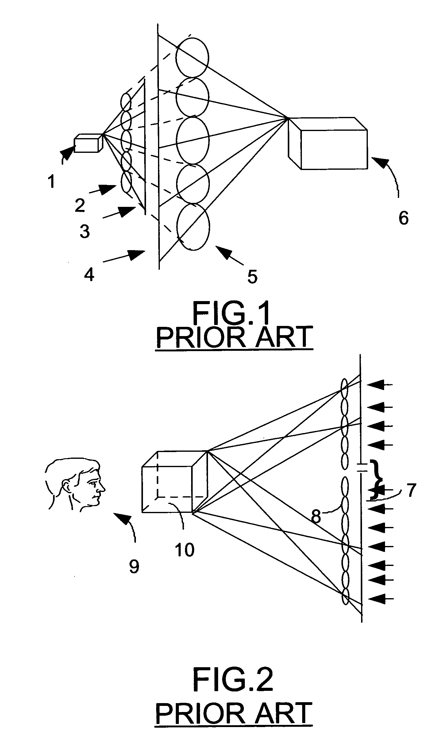
[0042] The same principle of magnification and projection described in the 3-D PATENTS, is used in the present invention. The difference is that video and digital imaging is used instead of photographic film. Consequently, the integral photographs of the 3-D PATENTS, do not physically exist in the present invention. Instead, they are virtual digitizations initially created with video imaging tubes and subsequently stored as digital information in computer memory and peripheral media. Virtual integral photographs produced in this manner are novel. The actual scenes are photographed using camera embodiments described herein. Many of the camera optical systems resemble those of the cameras described in the 3-D PATENTS. However, as will be described herein, because of image resolution problems, multiple video imaging tubes must be used. In most of the camera embodiments described, a single integrated first active optical system is used with a plurality of imaging devices. Yet, in one of the embodiments, a plurality of conventional video cameras functioning together as a single unit are used to produce the digitized virtual integral photograph. This camera embodiment is reminiscent of the earlier prior art discussed above. This is only an external physical resemblance due to the use of multiple cameras in the inventions dating back to the nineteenth century. However, when considered as a unit, this camera embodiment is not at all anticipated nor predicted by the aforementioned prior art. An integral photograph is composed of a plurality of elemental photographs, each elemental photograph requiring a separate lens for its creation. Whether that lens belongs to an integrated optical system or is a component of a separate single camera is irrelevant. A single camera with multiple lenses and imaging devices is the equivalent of the same number of multiple cameras havi...

Problems solved by technology

Yet, the information recording and retrieval requirements for a single frame or photograph of a three-dimensional picture using the system described in the 3-D PATENTS are so great as to exceed the resolution capabilities of even this film.
The film stabilization requirements make great demands upon the projector.
Also, illumination demands are great, and very complex unmultiplexing optics are required for the projector.
Clearly, both the motion picture camera and the projector for the system disclosed in the 3-D PATENTS are much more expensive to fabricate than their current motion picture equipment counterparts.
The fact that the camera is very expensive should not discourage its use since even its higher cost would represent a small fraction of the cost of currently producing a motion picture.
History of the motion picture industry has demonstrated that special processes requiring special theaters to be built have not enjoyed enduring economic success.
However, the projector is the most expensive component in a theater designed to display these three-dimensional motion pictures.
Unfortunately, the resolution available from conventional television systems makes projection of motion pictures before large audiences in large theaters impractical.
Rear projection large screen video home entertainment systems are popular, but the video quality is much lower than with large screen conventional picture tubes.
While the quality of these pictures is acceptable to audiences attending such events, the quality of motion pictures so projected is very poor compared to the quality of conventional movies projected from film.
Some attempts have been made to digitally project popular movies in a few theaters with limited success.
The major drawback to currently available video projection systems is that the resolution is so poor compared to film projection that the audience must be seated far enough away from the screen so as not to notice the difference.
This poor image quality would probably be acceptable to viewers were film projectors not to be the motion picture display standard.
However, audiences always look for image quality improvement, and are unwilling to accept less than standard viewing conditions.
The bandwidth is simply too low.
Other transmission methods, such as fiber optic cable, have sufficient bandwidth, but the NTSC, PAL, SECAM, and even the HDTV display standards do not provide enough monitor resolution to show these movies.
However, the NTSC, PAL, or SECAM standards used therein do not adequately take advantage of the capabilities of digital video.
With many computers, the amount of information required to record an entire motion picture on the available storage media may be so large as to make such recording impractical.
Therefore, the current image formats are inadequate to meet the resolution requirements of the three-dimensional process disclosed herein.
In this case, the editors were unable to store the entire movie on their computer at one time.
Unfortunately, these also are matched to current television sets or computer monitors, and are unsuitable for use with the three-dimensional motion picture format disclosed herein.
On the other hand, generalized data compression algorithms are not necessarily keyed to photographs or video files that require display on television sets or monitors.
Unfortunately, they were confronted with bandwidth problems.
Uncompressed video at 216 Mbps and above cannot be transmitted using these methods of data delivery.
An additional problem arises when a user downloads a program from a host computer.
The problems with currently available video streaming technology are the dependence upon relatively low available bandwidths and the incapability of producing programming with acceptable resolution on commercially available computer monitors.
Even were these problems to be solved for conventional video programming, it would not be even nearly adequate for the much higher data transfer rates required for three-dimensional motion pictures produced using the process disclosed herein.
As the 3-D PATENTS' disclosure proceeded, it became apparent that, once the basic principle of magnification and projection was utilized, the primary technological problem centered around practically recording a sufficient quantity of information upon a manageable amount of photographic film.
In the Present Invention, it will become apparent that, once “the principle of magnification” is employed, the primary technological problem centers around practically recording a sufficient quantity of information on digital recording devices as well as on digitally compatible recording media.
Another major technological problem, the solution to which is addressed in the Present Invention, is integration and transmission of the vast quantity of digital information using digital electronics so as to photograph large three-dimensional scenes and to project or transmit the three-dimensional pictures produced therefrom onto a screen for viewing.
Furthermore, while broadcasting of three-dimensional photographic material over conventional television broadcast bands or even over conventional cable TV transmission is unfeasible due to bandwidth considerations, it is possible to adequately transmit such image information over closed circuit fiber optics cable.
Projection of non-stereoscopic three-dimensional motion pictures in theaters was heretofore unfeasible.
However, as will be described herein, because of image resolution problems, multiple video imaging tubes must be used.
However, when considered as a unit, this camera embodiment is not at all anticipated nor predicted by the aforementioned prior art.
The number of elemental photographs so created is insufficient to combine to produce an adequately viewable three-dimensional scene.

Method used


Image

  • System and apparatus for recording, transmitting, and projecting digital three-dimensional images
  • System and apparatus for recording, transmitting, and projecting digital three-dimensional images
  • System and apparatus for recording, transmitting, and projecting digital three-dimensional images

Examples


third embodiment

2.4 the Camera

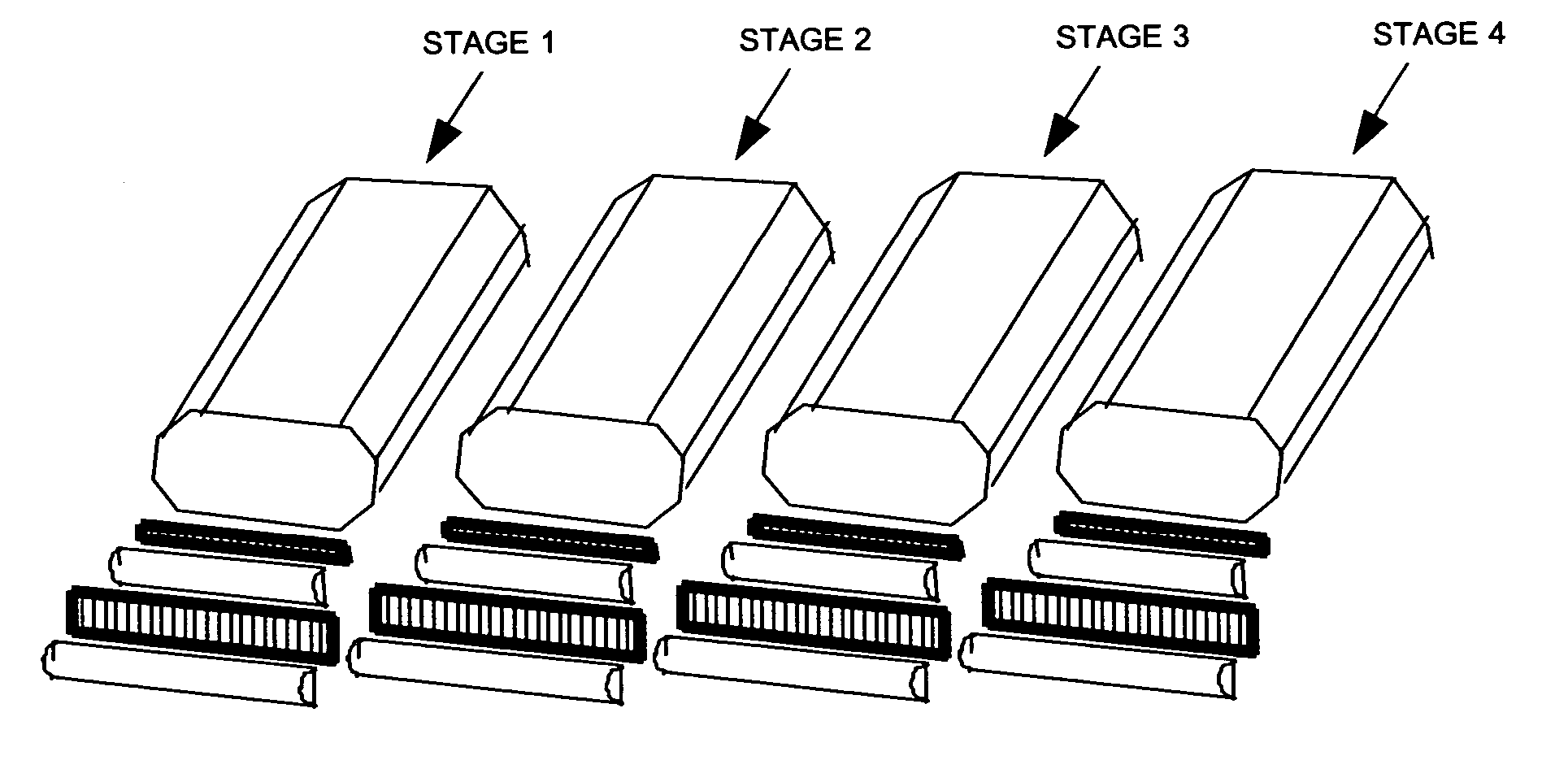
[0141] A third solution to the problem exists that would permit the use of a single conventional video low resolution imaging tube. This third embodiment of the camera would involve optically magnifying each elemental picture and focusing the magnified image onto the surface of the imaging tube. This method has the advantage of providing high resolution pictures, but has the disadvantage that much higher data transfer rates are required. For example, if normal film moves at 25 fps and there are 1,800 elemental pictures, then information would have to be transferred at the rate of 45,000 fps. Video camera electronics that provide such a high transfer rate are not commercially available. Furthermore, the electron beam scan rate of the video imaging tube is not that high. Multiple video imaging tubes can be used to alleviate the scan rate problem. In the extreme case, the number of video imaging tubes can be equal to the number of elemental pictures. However, a camera of ...

fourth embodiment

2.5 the Camera

[0142] A fourth solution to the problem exists that would employ high resolution line scan image sensors rather than area scan image sensors. A line scan image sensor captures image data by scanning a single line while an area scan image sensor scans an entire image surface one line at a time. Line scan image sensors are generally used for document scanning and optical character recognition while area scan image sensors are commonly used for video applications. FIG. 9 shows a schematic of a line scan image sensor. The active element of a line scan image sensor 31 is a small rectangular area 32. Within that rectangular area are sensitized pixels that are able to capture image data. Electrode pins 33 plug the image sensor into the electronics of the device (e.g., a photocopy or a facsimile machine) where scanning is to occur. Most line scan image sensors have relatively low resolution. However, high resolution line scan image sensors are commercially available. For examp...

fifth embodiment

2.6 the Camera

[0144] As an alternative fifth embodiment, the scanning device 37 of FIG. 10 may be eliminated entirely. In that event, the sensor 38 must be moved to accept the entire image. The advantage of doing this would be the elimination of optics that can potentially distort the image. The disadvantage of this alternative is that a 25-50 cps vibration would be set up that could destabilize the camera. However, once again, techniques exist that could stabilize the camera.

2.7 General Discussion Pertaining to the First Five Camera Embodiments

[0145] The camera used in this process, whether film or video, is very large relative to current motion picture camera equipment. The size of the camera horizontally is dictated by the size requirements of the matrix lens array. The width of the array is between 1½ and 2 meters, and its height is one-half of the width. The camera housing must encompass the external optics (i.e., the horizontal cylindrical lens(es), the matrix lens array(s)...


PUM


Abstract

A system and method for recording and reconstructing uniformly magnified three-dimensional images from digital representations of integral photographs. Several camera and projector embodiments are provided along with a means for direct transmission without projection to a special screen that reconstructs the three-dimensional images. This invention is particulary applicable to showing non-stereoscopic three-dimensional motion pictures that reconstruct from integral photographs or holograms that may be viewed without the need for special glasses.

Description

CROSS REFERENCE TO RELATED APPLICATIONS [0001] This non-provisional patent application is a National Stage Entry of PCT Patent Application Serial ______, fled Dec. 8, 2004 under 35 U.S.C. § 371, which in turn is a continuation-in-part of and claims the benefit of and priority to U.S. Provisional Application Ser. No. 60 / 481,823, filed Dec. 21, 2003. Said PCT Application and Provisional Application (hereinafter the claimed Priority Applictions) are hereby incorporated by reference herein in their entirety thereto. This application contains material that was disclosed in my Disclosure Document No. 529418 filed with the United States Patent and Trademark Office on Apr. 7, 2003 and retained on deposit under the Disclosure Document Program discussed in MPEP §1706. This application discloses an invention that is an improvement over my U.S. Pat. No. 6,229,562 granted on May 8, 2001, incorporated herein in its entirety by reference thereto, and my U.S. Pat. No. 6,593,958 granted on Jul. 15, ...

Claims


Application Information

Patent Timeline
IPC IPC(8): H04N13/04H04N11/04H04N7/12H04N15/00H04N11/02H04B1/66H04N7/26H04N13/363
CPCH04N13/0029H04N13/0055H04N13/0059H04N13/0228H04N13/0242H04N19/597H04N13/0404H04N13/0422H04N13/0459H04N13/0497H04N19/00H04N13/0402H04N13/302H04N13/305H04N13/243H04N13/194H04N13/189H04N13/324H04N13/229H04N13/363H04N13/139H04N13/398
Inventor KREMEN, STANLEY H.
Owner KREMEN STANLEY H
Features
  • Generate Ideas
  • Intellectual Property
  • Life Sciences
  • Materials
  • Tech Scout
  • Unparalleled Data Quality
  • Higher Quality Content
  • 60% Fewer Hallucinations
Learn More