
Mobile communication system, UE, handover control method for use thereof and program thereof

Inactive Publication Date: 2006-02-23
LENOVO INNOVATIONS LTD HONG KONG
View PDF8 Cites 9 Cited by
  • Summary
  • Abstract
  • Description
  • Claims
  • Application Information

AI Technical Summary

Benefits of technology

[0011] Therefore, an object of the present invention is to obviate the problems noted above and provide a mobile communication system, a UE, a handover control method for their use and its program permitting, in handover control of UEs, effective utilization of reception resources (hardware and software) which each UE has and thereby facilitating steady communication.
[0033] Also, the UE may then achieve a further gain in total communication quality by allocating the finger used for reception from the cell to be temporarily cut off to the multi-path components of the remaining cells.
[0040] In this way, in the mobile communication system according to the present invention, it is made possible in the handover control of UE to perform steady communication by effectively utilizing the limited reception resources (hardware and software) available to the UE. The mobile communication system according to the present invention also enables the system capacity (the number of accommodable users) of the whole network to be increased.
[0043] According to the present invention, by using the configuration and operations to be described below, it is made possible in the handover control of a UE to effectively utilize the limited reception resources (hardware and software) available to the UE and thereby to perform steady communication.

Problems solved by technology

In the conventional handover control described above, there is a limit to the number of cells to which a UE can perform a handover or to the number of receivers (fingers) among which rake synthesis is possible (e.g. six cells or 12 fingers), but much of the capacity within this limit may be occupied by cells whose DPCH quality is poor.
Furthermore, transmission power on a DPCH from a cell whose DPCH is poor in communication quality not merely is unnecessary for this UE but also interferes with other UEs (e.g. other users), and therefore adversely affects the downlink capacity (user capacity) of the whole system.

Method used


Image

  • Mobile communication system, UE, handover control method for use thereof and program thereof
  • Mobile communication system, UE, handover control method for use thereof and program thereof
  • Mobile communication system, UE, handover control method for use thereof and program thereof

Examples


Embodiment Construction

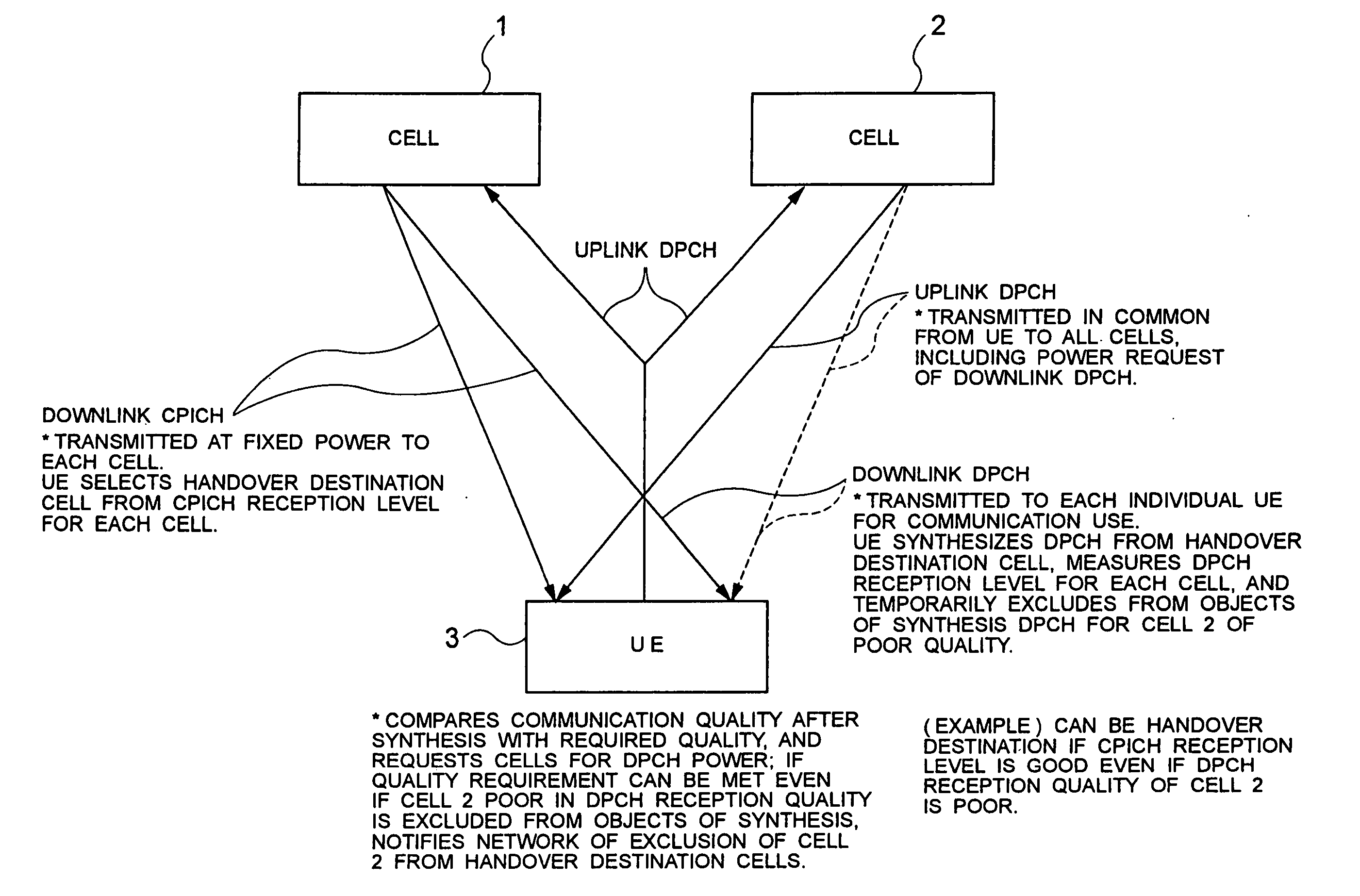
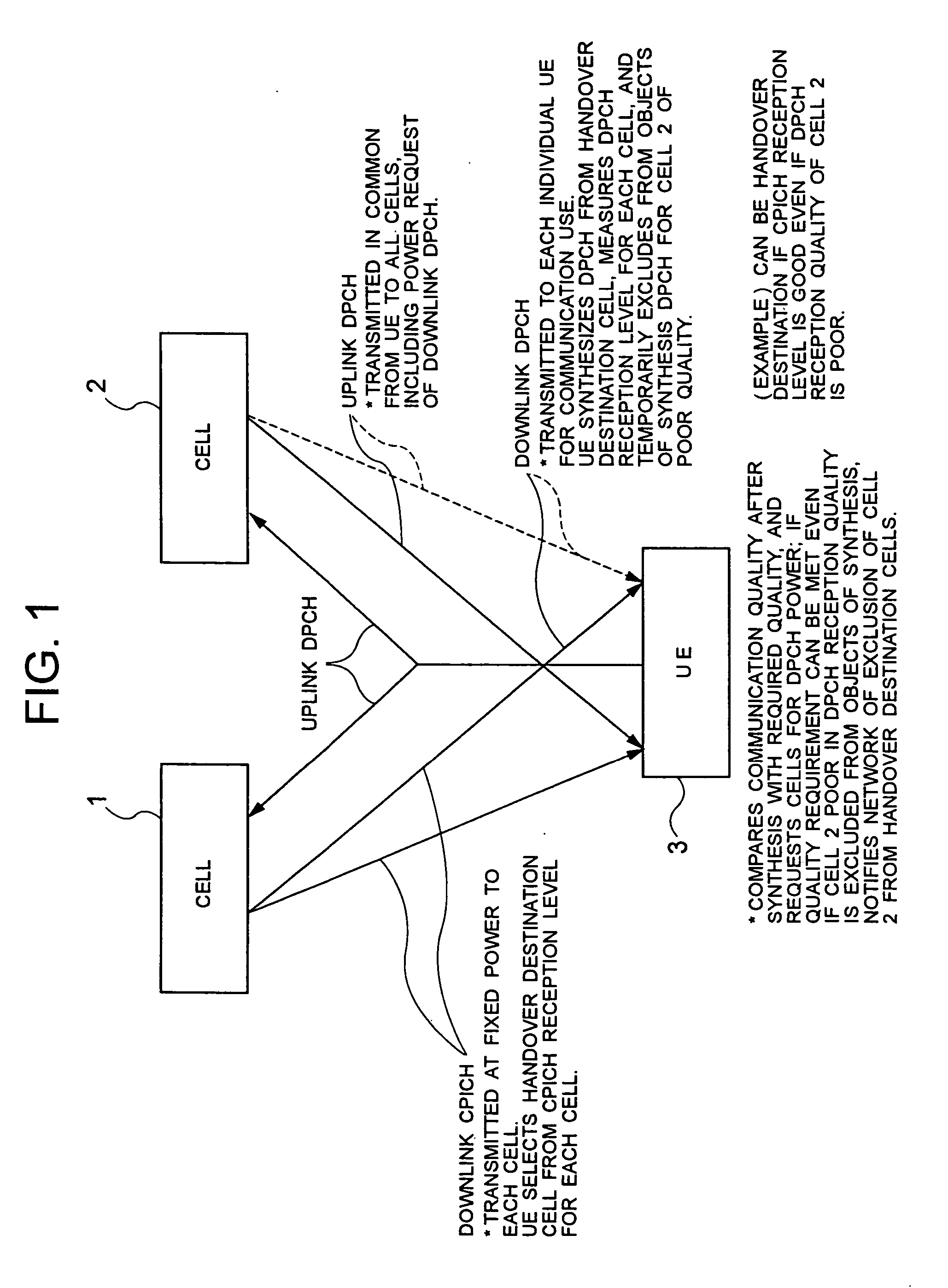
[0056] Next, a preferred embodiment of the present invention will be described with reference to accompanying drawings. FIG. 1 is a block diagram showing the configuration of a mobile communication system, which is an embodiment of the invention. Referring to FIG. 1, the mobile communication system of the embodiment comprises base stations (not shown) (cells 1 and 2 corresponding to those base stations are shown FIG. 1) and a UE 3 of the CDMA system. Although the base stations are controlled by a RNC (Radio Network Controller) (not shown), its description will be dispensed with here because control by the RNC has no direct bearing on this embodiment.

[0057] The UE 3 performs reception from the downlink CPICH and the downlink DPCH for each of the cells 1 and 2, and transmission over an uplink DPCH in common for both cells 1 and 2.

[0058] Transmission over the downlink CPICH is performed at a fixed level of power for each of the cells 1 and 2, and the UE 3 selects the handover destina...


PUM


Abstract

The present invention provides a mobile communication system capable of effectively utilizing the limited reception resources available to the UEs and thereby performing steady communication for use in the handover control of UEs. A UE, during communication, determines a handover destination cell according to the result of measurement of the CPICH reception level of each of cells: (1) it measures the reception quality of the downlink DPCH of each of the cells and utilizes the result for the selection of the handover destination cell; (2) switches the handover destination cell and searches for a cell needed for obtaining required communication quality; (3) observes the displacement of the CPICH path loss of each of the cells; and (4) observes whether or not the downlink DPCH transmission power is controlled on the basis of the power request from the UE for each of the handover destination cells.

Description

BACKGROUND OF THE INVENTION [0001] 1. Field of the Invention [0002] The present invention relates to a mobile communication system, a UE (User Equipment), and a handover control method for their use and its program, and more particularly, to a handover control method for UEs of the CDMA (Code Division Multiple Access) system. [0003] 2. Description of the Prior Art [0004] In a handover control of a UE of the CDMA system, when a UE 13 is to select cells 11 and 12 to which the handover is to take place as shown in FIG. 12, the reception level of a CPICH (Common Pilot Channel) to be received in common within the cells 11 and 12 is measured, and the cells 11 and 12 whose reception level is satisfactory are selected for the handover (see Japanese Patent Application Laid-Open No. 2002-27522 for instance). [0005] More specifically, the selection is made on the basis of the CPICH RSCP (Received Signal Code Power) which is the code power of each of the cells 11 and 12 received by the UE 13, t...

Claims


Application Information

Patent Timeline
IPC IPC(8): H04Q7/20H04W36/08H04W36/20H04W36/30H04W36/36
CPCH04B1/7115H04W36/08H04W52/40H04W36/36H04W36/30H04W36/00835H04W36/0083
Inventor HOKAO, TOMOAKI
Owner LENOVO INNOVATIONS LTD HONG KONG
Learn More