Data access responding system, storage system, client apparatus, cache apparatus, and method for accessing data access responding system

a data access and responding system technology, applied in the field of data access responding system, can solve the problems of complex procedure carried out after the commencement of data transfer, long waiting time required for actually starting data transfer, etc., and achieve the effect of effectively utilizing the cache area of the client apparatus and shortening the waiting tim

Inactive Publication Date: 2006-02-23
FUJITSU LTD
View PDF3 Cites 263 Cited by
  • Summary
  • Abstract
  • Description
  • Claims
  • Application Information

AI Technical Summary

Benefits of technology

[0023] In the control apparatus according to the second aspect of the present invention, it is possible to directly access the cache apparatus and carry out RDMA process, by storing information of the storage location of the data in the cache area, for which data an access frequency to the cache apparatus is high. Accordingly, it is possible to shorten the latency required along with access request made by the client apparatus.
[0024] Further, the control apparatus may manage an access frequency to the data stored in the cache apparatus, and may delete the information of the storage location for the data for which the access frequency lowers, at any time. Thereby, it is possible to effectively utilize the cache area of the client apparatus. It is noted that, management of the access frequency may be made by client apparatus, and the client apparatus may request the control apparatus for the information of the storage area of the data when determining the data has a high access frequency.
[0025] Further, the client apparatus according to the second aspect of the present invention can search for the information of the storage location from the cache area when making an access request for the data for which the storage area is managed by the control apparatus, and, can directly access the cache apparatus so as to have the relevant data transferred thereto without making an access request to the control apparatus when determining that the relevant data is stored in the cache apparatus from the information stored in the cache area. Further, when the access request is accompanied by writing processing, it is possible to achieve storage data consistency as in the above-described first aspect of the present invention by copying the data once written in the cache apparatus also to the storage apparatus.

Problems solved by technology

Accordingly, a latency (waiting time) required for actually starting the data transfer may be long, and also, a procedure carried out after the commencement of the data transfer may be complicated.

Method used


Image

  • Data access responding system, storage system, client apparatus, cache apparatus, and method for accessing data access responding system
  • Data access responding system, storage system, client apparatus, cache apparatus, and method for accessing data access responding system
  • Data access responding system, storage system, client apparatus, cache apparatus, and method for accessing data access responding system

Examples


first embodiment

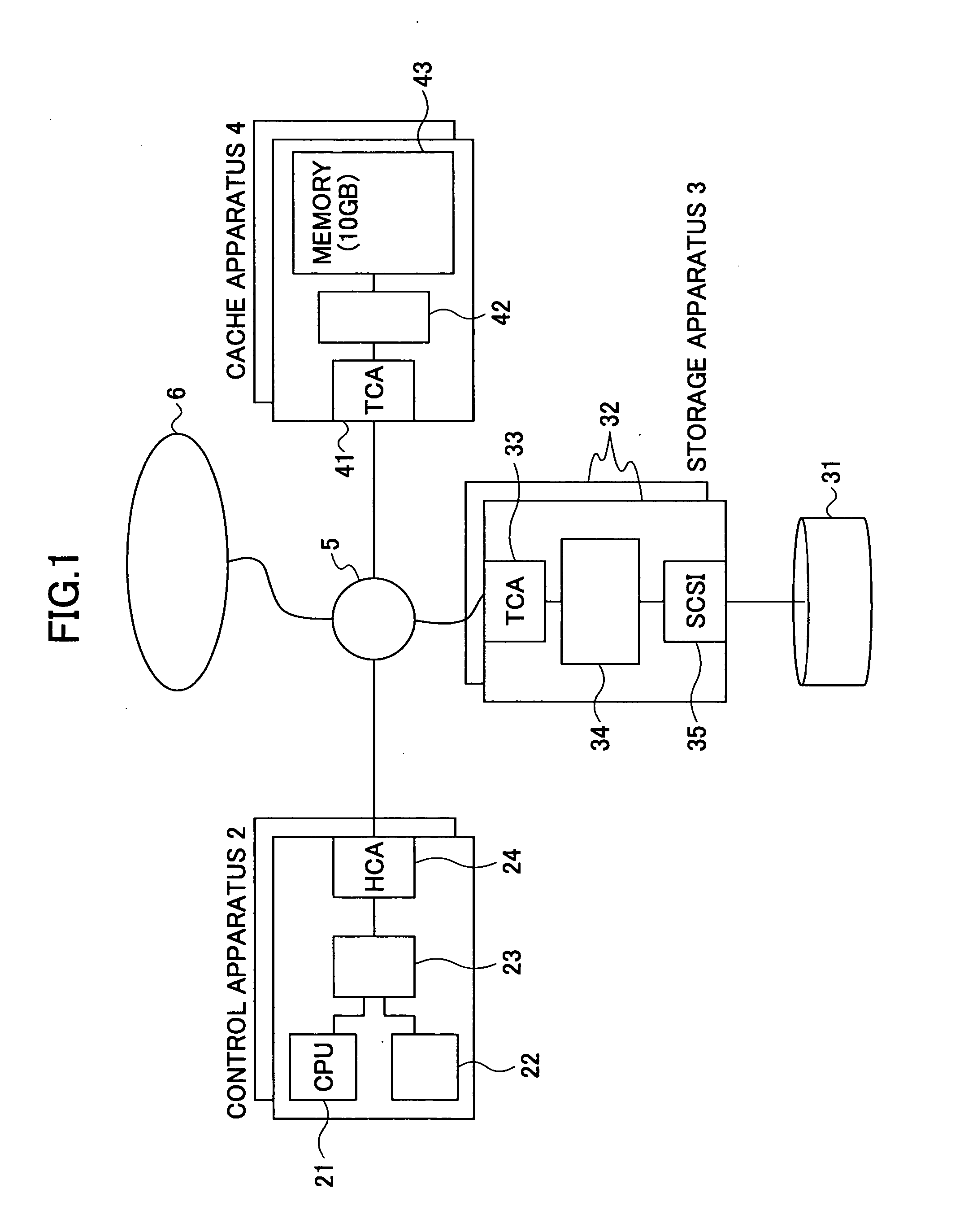
[0046]FIG. 1 shows a configuration of a data access responding system according to the present invention.

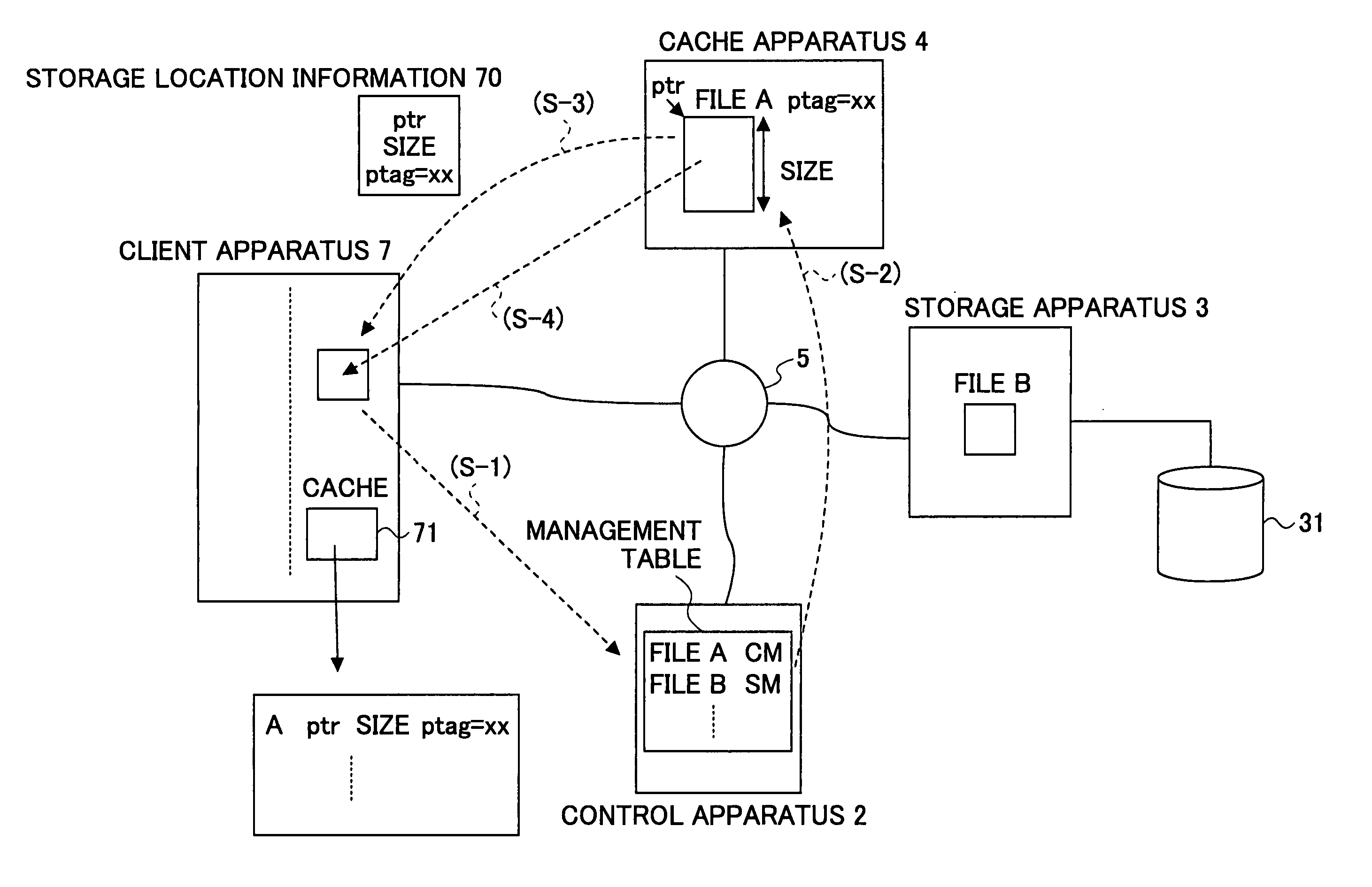
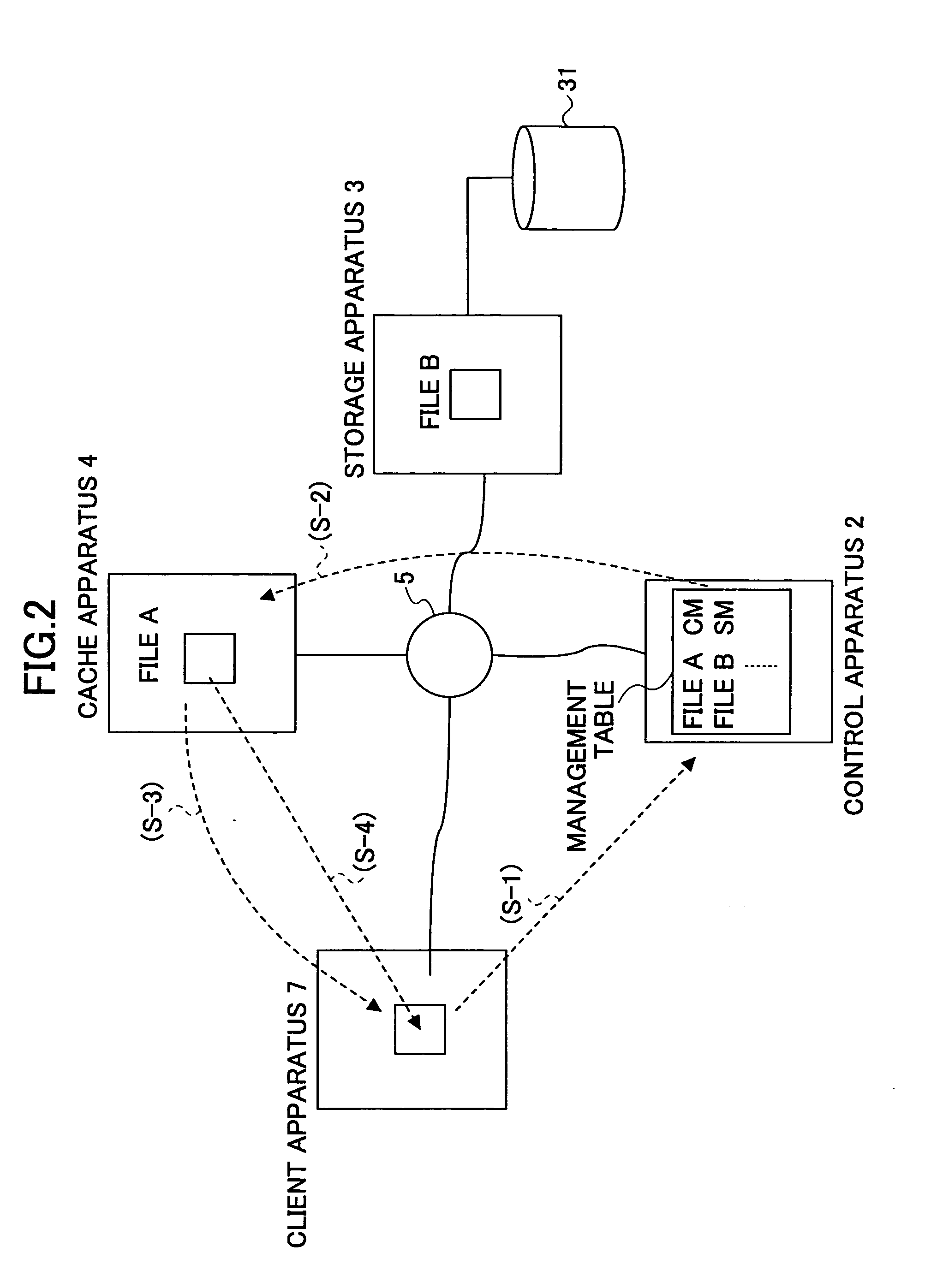
[0047] The data access responding system according to the first embodiment includes a client apparatus 6 group including a plurality of client apparatus 7 which are PCs or WSs connected via a communication network 5; a storage apparatus 3 connected with the client apparatus group 6 via the communication network 5; a cache apparatus 4 acting as a cache of data stored in the storage apparatus 3; and a control apparatus 2 which is a WS managing storage locations of data stored in the storage apparatus 3 and in the cache apparatus 4.

[0048] Each of the respective client apparatuses 7 of the client apparatus group 6, the stogie apparatus 3, the cache apparatus 4 and the control apparatus 2 has a communication function, and, therewith, each client apparatus 7, the storage apparatus 3, the cache apparatus 4 and the control apparatus 2 can mutually communicate via the communication netwo...

second embodiment

[0112] the present invention is described now.

[0113] According to the second embodiment of the present invention, in comparison to the above-described first embodiment, information concerning a cache area in the client apparatus 7 is notified of to the control apparatus 2. Then, storage location information of data for which an access frequency is high in the cache apparatus 4 can be written in the cache area of the client apparatus 7. Other than this point, the configuration of the data access responding system and the function of the client apparatus 7 making access requests are the same as those of the first embodiment. Accordingly, relationship between the client apparatus 7 and the control apparatus 2 different from that of the first embodiment is described.

[0114]FIGS. 15 through 17 shows processing of communicating information of the cache area or the storage location information between the client apparatus having the cache area in a memory and the control apparatus managing...

third embodiment

[0138] the present invention is described now.

[0139] In the third embodiment, in comparison to the above-described second embodiment, the client apparatus 7 itself manages the access request frequency, and, based on the management result, the client apparatus 7 requests the control apparatus 2 to write the storage location information for the data for which the access frequency is high in the cache area 72 of its own. Other than this point, the third embodiment is the same as the second embodiment, and only the different point is described.

[0140]FIGS. 22 and 23 show processing of the client apparatus 7 requesting the control apparatus 2 to register the storage location information according to the access frequency managed by itself, in the data access responding system according to the third embodiment of the present invention. FIG. 24 shows a sequence chart of the same processing.

[0141] The data access responding system according to the third embodiment shown in FIGS. 22 and 23 i...


PUM


Abstract

A control apparatus provides a transfer instruction to one of storage apparatus and a cache apparatus, in which relevant data is stored, when receiving an access request from a client apparatus for the data for which the storage location is managed; and the one of the storage apparatus and the cache apparatus receiving the transfer instruction directly returns a reply message, to the client apparatus, having information of the storage location of the data added thereto, which data the access request requests.

Description

CROSS-REFERENCE TO RELATED APPLICATION [0001] This application is a U.S. continuation application filed under 35 USC 111(a) claiming benefit under 35 USC 120 and 365(c) of PCT application JP03 / 06354, filed May 21, 2003. The foregoing application is hereby incorporated herein by reference.BACKGROUND OF THE INVENTION [0002] 1. Field of the Invention [0003] The present invention relates to, in particular, an art of accessing a storage apparatus such as a hard disk apparatus or such from a client apparatus such as a personal computer (simply referred to as a ‘PC’ hereinafter) or a work station (simply referred to as a ‘WS’, hereinafter). [0004] 2. Description of the Related Art [0005] A so-called storage system has been applied for a wide variety of fields, in which, for example, a storage apparatus such as a hard disk apparatus is physically connected to a client apparatus such as a PC, a WS or such, via an interface such as an SCSI (small computer system interface), an FC (fiber chann...

Claims


Application Information

Patent Timeline
Patent Type & Authority Applications(United States)
IPC IPC(8): G06F15/16G06F13/00G06F3/06G06F12/00G06F17/30
CPCG06F3/0611G06F3/0659G06F3/0683G06F2212/463G06F2212/263G06F2212/314G06F12/0868
Inventor OE, KAZUICHI
Owner FUJITSU LTD
Why Eureka
Try Eureka