Gas analysis method and ionisation detector for carrying out said method

a technology of ionisation detector and gas analysis method, which is applied in the direction of dispersed particle separation, instruments, separation processes, etc., can solve the problems of large detector dimensions, inability to make a direct qualitative analysis (to identify the impurity atom or molecule) or quantitative analysis (to measure the impurity concentration) one, etc., to achieve optimal radiation utilization

Inactive Publication Date: 2006-03-02
KUDRYAVTSEV ANATOLY ANATOLIEVICH +1
View PDF9 Cites 13 Cited by
  • Summary
  • Abstract
  • Description
  • Claims
  • Application Information

AI Technical Summary

Benefits of technology

[0006] To reach this aim, the nearest analog for gas impurities detection from prior art, in which impurity atoms or molecules are ionized in collisions with particles of definite energy in an ionization chamber; the current across at least one of two electrodes located in the chamber is measured as a function of the voltage applied between said two electrodes, have been modified, as follows. According to the present invention, the pressure of the main gas and the ionization chamber geometry are to be chosen in such a way that a distance from any point inside of the chamber to the nearest wall or to one of said electrodes is less than a mean length of electrons displacement before they lose a prescribed portion of their kinetic energy. Also, equipotential space inside of said ionization chamber, where ionizing collisions occur, is to be provided. Also, a number of electrons with characteristic energy values produced in ionization of said atoms or molecules is determined from the current dependence on the voltage applied. Also, the data on the electron parameters are used to identify and determine the impurity species in the gas. This technical approach allows making a qualitative and quantitative analysis of a wide class of gaseous mixtures, using some kinds of main gas in various concentrations. The implementation of this technique is simple and compact because one needs only electrodes, a source of ionizing particles of definite energy, and appropriate means for registration of the electric current as a function of the applied voltage.
[0027] Moreover, according to the present invention, the radiation source in the ionization detector may be filled with argon (Ar) and comprise a cylindrical window transparent to resonant radiation, two electrodes at the butt-ends of said window and a power source to ignite a gas glow discharge; the anode, cathode and the grid for photoelectron detection may be made as plane-parallel rings arranged co-axially and around of said cylindrical window; the radiation traverses only the space between the anode and the grid. This arrangement of the power source and the detection electrodes provides the optimal utilization of the radiation for photo-ionization because there is a large solid angle, in which the radiation passes into the space between the anode and the grid.

Problems solved by technology

One of disadvantages of these prior art approaches are large detector dimensions, because the ions with the different charge-to-mass ratio are selected and detected separately in a mass-spectrometer after a flight along a trajectory of definite length.
Another disadvantage is the necessity to maintain a fairly high vacuum along this trajectory to prevent the ions from scattering in collisions with residual gas molecules.
However, the nearest analog in question provides only an ascertainment of the fact that an impurity has appeared in the main gas but it fails to make a direct qualitative analysis (to identify the impurity atoms or molecules) or quantitative (to measure the impurity concentrations) one.

Method used


Image

  • Gas analysis method and ionisation detector for carrying out said method
  • Gas analysis method and ionisation detector for carrying out said method
  • Gas analysis method and ionisation detector for carrying out said method

Examples


Embodiment Construction

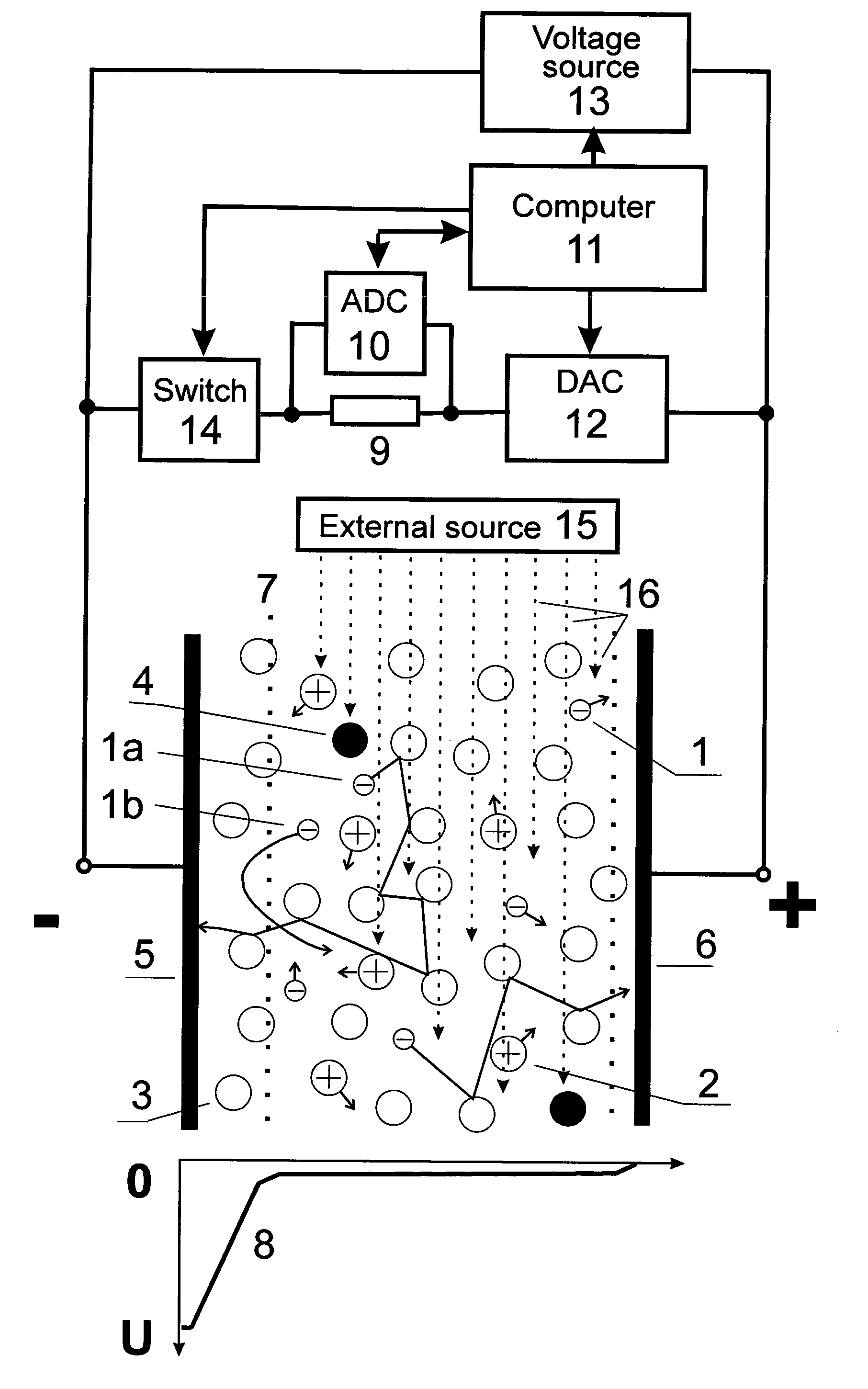
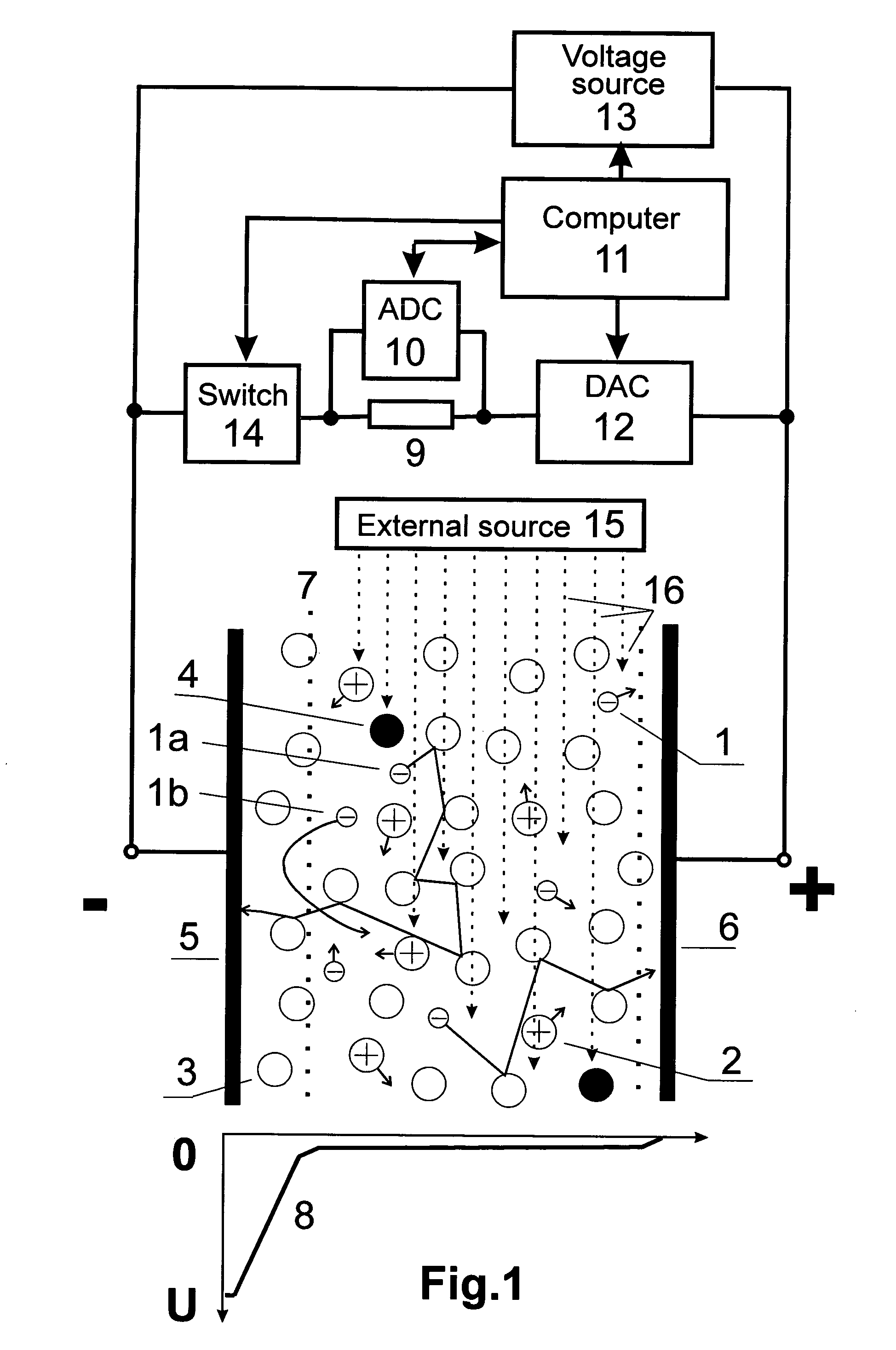
[0037] The technical designs to implement the suggested method of gas analysis and the ionization detector are based on a qualitative model of the physical processes to be described below. The concrete details of the physical model described don't affect a broad understanding of the basic features of the present invention.

[0038] When atoms or molecules of an impurity A collide with particles B*, having a definite energy Ep, they become ionized to produce free electrons {overscore (e)}, if the B* particles energy is high enough:

A+B*→A++B+{overscore (e)}  (1)

[0039]FIG. 1 shows schematically electrons 1 and impurity ions 2 produced by the collisions, as well as main gas atoms 3. As the particles of a definite energy Ep there may be used, e.g., metastable or resonant excited atoms of the main gas 4 (the main gas also be referred as a buffer gas). Additionally, one can use photons with a given energy Ep from an external source as said particles of a definite energy. The electrons rele...


PUM

PropertyMeasurementUnit
pressureaaaaaaaaaa
energy gapaaaaaaaaaa

Abstract

A method of gas analysis and an ionization detector for its implementation provide a qualitative and quantitative analysis of impurities in a main (buffer) gas. The detector can operate in a wide range of gas pressures, up to atmospheric one. The identification of impurities is provided by analyzing the energy of electrons produced by the ionization of the impurity atoms or molecules in their collisions with long living atoms of a buffer gas or with monochromatic photons. The energy analysis of electrons produced in the collisions of impurities with metastable atoms in the afterglow plasma ignited between two plane electrodes is performed by determining the second derivative of electric current dependence on the voltage applied between the anode and the cathode. The electron energy can also be analyzed by positioning a grid between the anode and the cathode and by using an external ultraviolet radiation source to ionize the impurities in the equipotential space between the grid and the anode. The inter-electrode gap and the gas pressure are chosen in such a way that the distortions in the electron energy measurement due to the collisions with the gas atoms or molecules should not exceed a prescribed value.

Description

FIELD OF THE INVENTION [0001] This suggested invention relates to means for determination of gas mixtures composition and provides qualitative and quantitative analysis of chemical structure of impurities in a main (buffer) gas. BACKGROUND OF THE INVENTION [0002] There are known various gas detectors, in which the chemical composition is identified by mass analysis of ions occurring at the gas ionization (see, e.g. [1]). Measurement of the current of ions separated with respect to their charge-to-mass ratio provides determination of the qualitative and quantitative composition of the gas mixture. A common feature of these prior art methods with the one we are suggesting, is the ionization of impurities at an ionization chamber. One of disadvantages of these prior art approaches are large detector dimensions, because the ions with the different charge-to-mass ratio are selected and detected separately in a mass-spectrometer after a flight along a trajectory of definite length. Anothe...

Claims


Application Information

Patent Timeline
Patent Type & Authority Applications(United States)
IPC IPC(8): B01D59/44G01N27/66
CPCG01N27/70G01N27/66
Inventor KUDRYAVTSEV, ANATOLY ANATOLIEVICHTSYGANOV, ALEXANDER BORISOVICH
Owner KUDRYAVTSEV ANATOLY ANATOLIEVICH
Why Eureka
Try Eureka