Contacts for CMOS imagers and method of formation

a technology of contact and imager, which is applied in the field of improved semiconductor imaging devices, can solve the problems of worm hole defects in the substrate, reduce imager performance, and and achieve the effect of less leakage into the substra

Active Publication Date: 2006-03-02
APTINA IMAGING CORP
View PDF57 Cites 37 Cited by
  • Summary
  • Abstract
  • Description
  • Claims
  • Application Information

AI Technical Summary

Benefits of technology

[0006] The present invention provides low leakage contacts to substrate nodes that require low leakage, such as a floating diffusion region or a photodiode. While examples using the imager floating diffusion (FD) contact will be provided, it is to be understood that this technology applies to any technology that requires low leakage junctions to substrate. In particular, this invention is applicable to CCD imagers, CMOS imagers, DRAM, SRAM, FLASH, Micro-processors, and logic devices, among others. This invention is applicable to forming both contacts to N+ and P+ junctions.
[0007] In an exemplary embodiment of the invention, at least one low leakage polysilicon contact is provided over a leakage sensitive area of a CMOS imager, such as the floating diffusion region or the photodiode. The polysilicon contact comprises a polysilicon region in direct contact with the area of interest (the leakage sensitive area) and a metal region located over the polysilicon region. The polysilicon contact provides an improved ohmic contact with less leakage into the substrate. The polysilicon contact may also be provided in integrated circuit structures that have conventional metal contacts, which are employed in areas of the CMOS imager that do not require low leakage.
[0008] Other exemplary embodiments provide a method of forming single level polysilicon contacts to connect leakage sensitive areas of a CMOS imager, such as the floating diffusion region or the photodiode, to various other CMOS imager structures. The single level polysilicon contact process comprises the steps of: (i) selectively adding polysilicon to low-leakage contact areas; (ii) optionally not adding polysilicon to some contact areas (i.e., contact areas which are not leakage sensitive); (iii) adding metal to both the polysilicon in the leakage sensitive contact areas and to the remaining contact areas which are not leakage sensitive; and (iv) providing a metal contact metallization that is self-aligned to the low leakage polysilicon contact.
[0009] The above and other advantages and features of the invention will be more clearly understood from the following detailed description which is provided in connection with the accompanying drawings.

Problems solved by technology

This reaction results in the formation of silicon fluoride which can create worm hole defects in the substrate.
Thus, leakage into the substrate reduces imager performance.

Method used


Image

  • Contacts for CMOS imagers and method of formation
  • Contacts for CMOS imagers and method of formation
  • Contacts for CMOS imagers and method of formation

Examples


Embodiment Construction

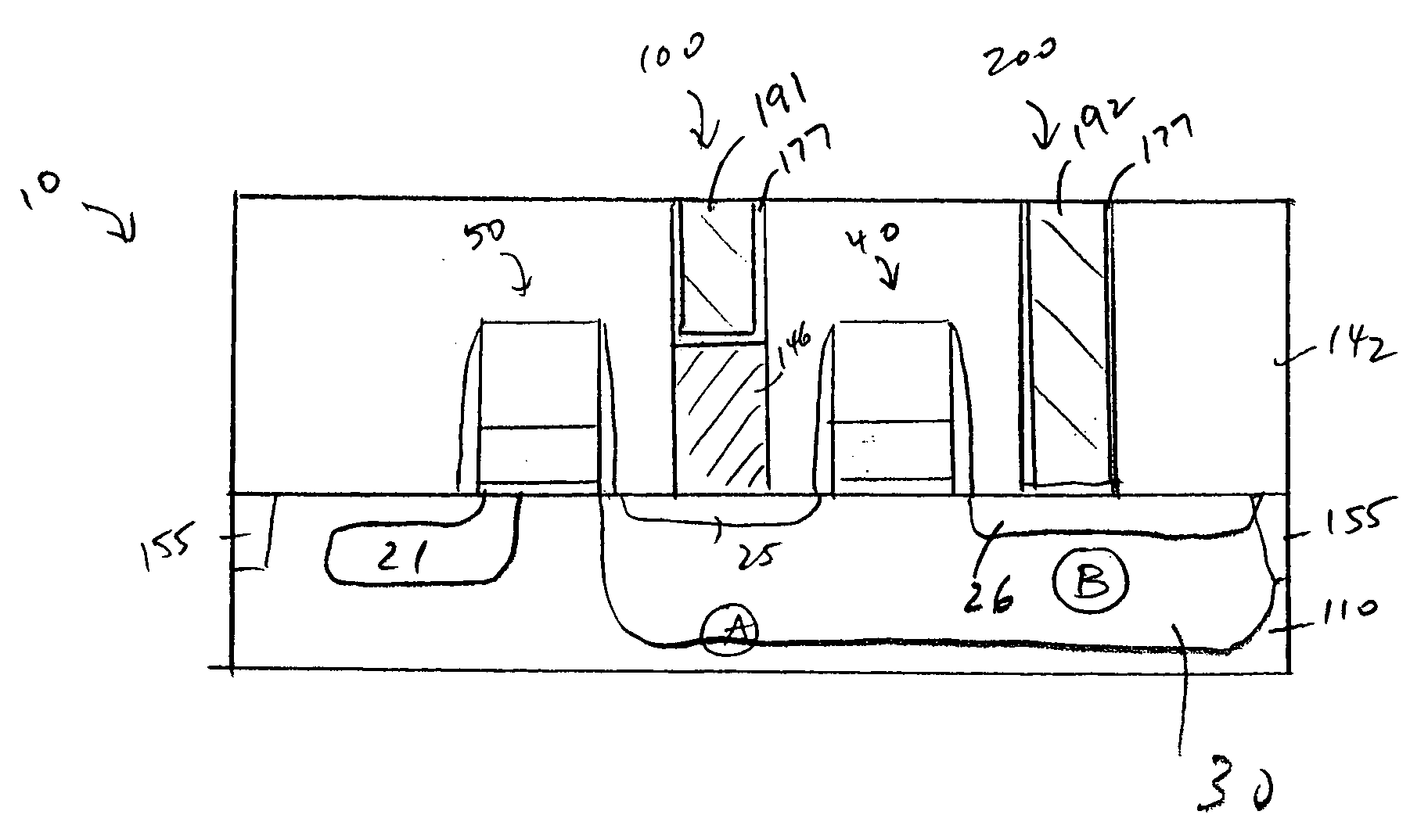
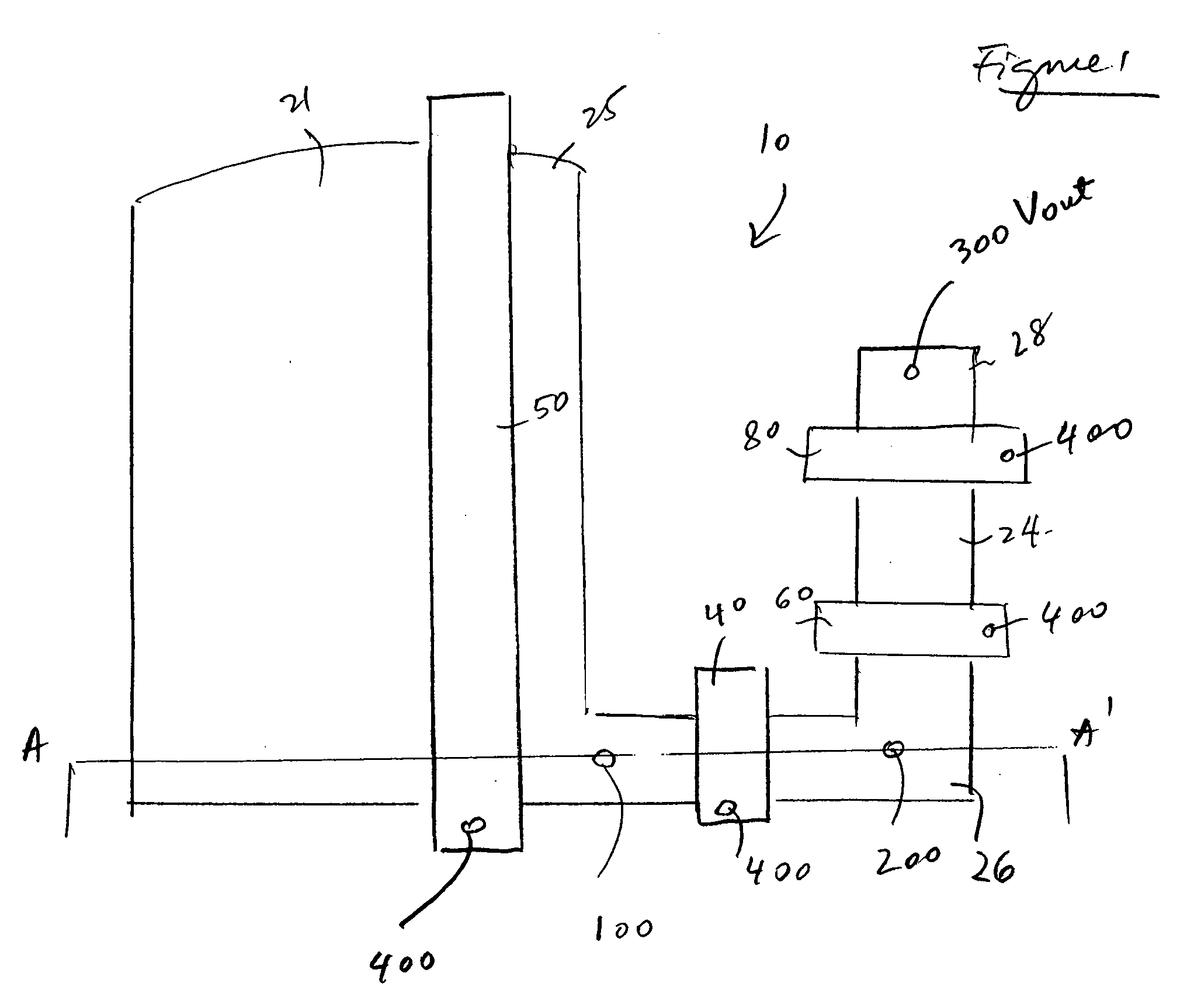
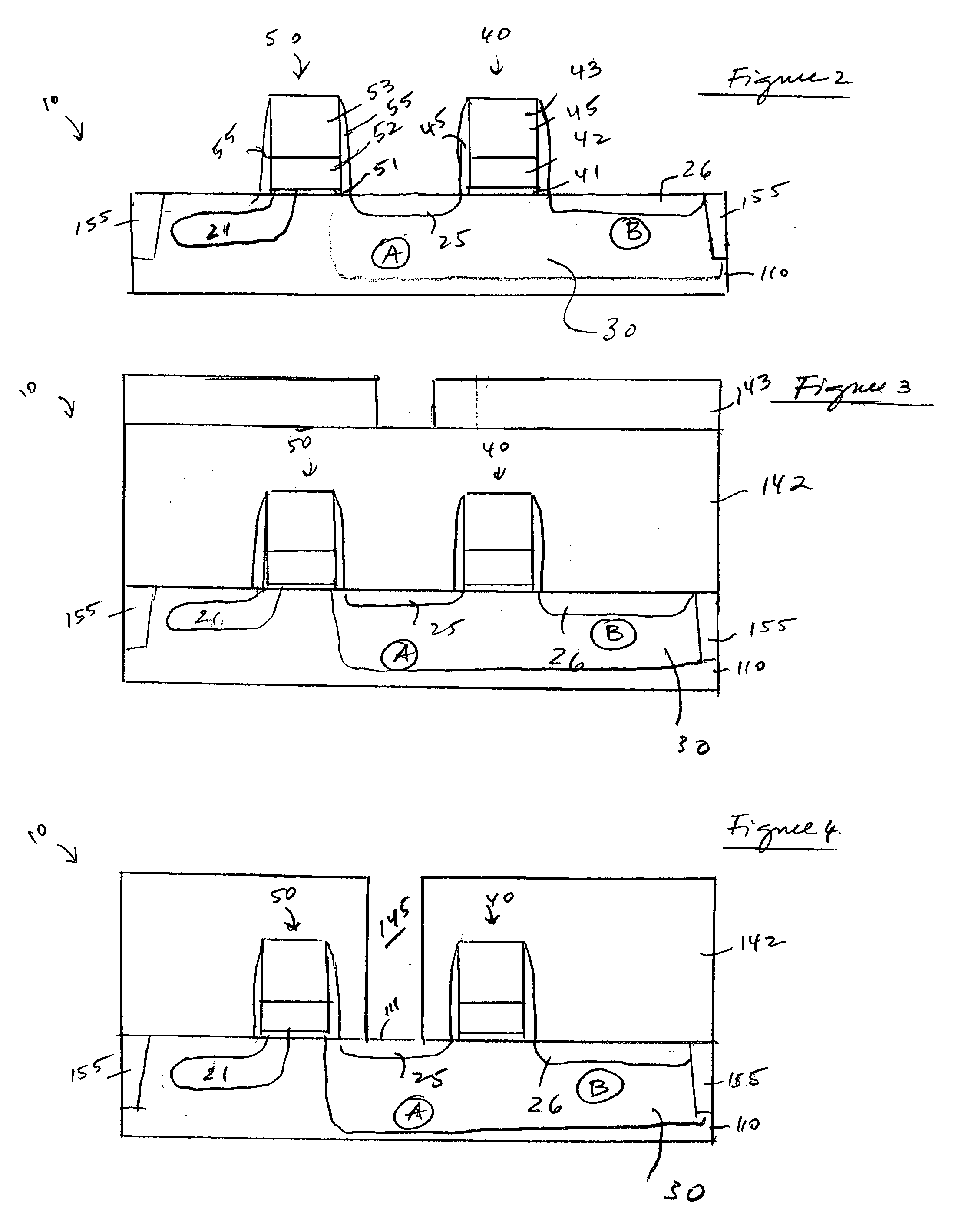
[0027] In the following detailed description, reference is made to the accompanying drawings which form a part hereof, and in which is shown by way of illustration specific embodiments in which the invention may be practiced. These embodiments are described in sufficient detail to enable those skilled in the art to practice the invention, and it is to be understood that other embodiments may be utilized, and that structural, logical and electrical changes may be made without departing from the spirit and scope of the present invention.

[0028] The terms “wafer” and “substrate” are to be understood as including silicon-on-insulator (SOI) or silicon-on-sapphire (SOS) technology, doped and undoped semiconductors, epitaxial layers of silicon supported by a base semiconductor foundation, and other semiconductor structures. Furthermore, when reference is made to a “wafer” and “substrate” in the following description, previous process steps may have been utilized to form regions or junction...


PUM


Abstract

Low leakage contacts on leakage sensitive areas of a CMOS imager, such as a floating diffusion region or a photodiode, are disclosed. At least one low leakage polysilicon contact is provided over a leakage sensitive area of a CMOS imager. The polysilicon contact comprises a polysilicon region in direct contact with the area of interest (the leakage sensitive area) and a metal region located over the polysilicon region. The polysilicon contact provides an improved ohmic contact with less leakage into the substrate. The polysilicon contact may be provided with other conventional metal contacts, which are employed in areas of the CMOS imager that do not require low leakage.

Description

[0001] This application claims the benefit of U.S. Provisional Application Ser. No. 60 / 606,520, filed on Sep. 2, 2004, the entire disclosure of which is incorporated by reference herein.FIELD OF THE INVENTION [0002] The invention relates to improved semiconductor imaging devices and, in particular, to CMOS imagers with low leakage contacts. BACKGROUND OF THE INVENTION [0003] Drawbacks of the so-called three-transistor (3T) pixel cell or four-transistor (4T) pixel cell of a CMOS imager relate to contact junction leakage, signal loss and contact defects which occur in the contact between a floating diffusion region formed in a substrate and a gate of a source follower output transistor. When a tungsten plug process (which is the current contact metallization of choice) is used to contact the floating diffusion region, tungsten is deposited with tungsten fluoride and a reaction typically takes place between the tungsten fluoride and the substrate. This reaction results in the formation...

Claims


Application Information

Patent Timeline
Patent Type & Authority Applications(United States)
IPC IPC(8): H01L31/113H01L31/062
CPCH01L27/14636H01L27/14603H01L23/485
Inventor FAN, XIAOFENGMAURITZSON, RICHARD A.RHODES, HOWARD E.
Owner APTINA IMAGING CORP
Why Eureka
Try Eureka