Multibeam antenna

a multi-beam antenna and antenna technology, applied in the direction of slot antennas, antennas, basic electric elements, etc., can solve the problems of difficult ground plate disposal near the antenna, difficult to say that the adaptive array antenna is suitable for consumer use, complex system, etc., to reduce the size of the antenna apparatus, reduce the number of switches, and the effect of not impaired the effectiveness of the antenna elemen

Inactive Publication Date: 2006-03-02
SONY CORP
View PDF12 Cites 26 Cited by
  • Summary
  • Abstract
  • Description
  • Claims
  • Application Information

AI Technical Summary

Benefits of technology

[0022] In the multibeam antenna according to the present invention, it is possible to realize alternate use of parasitic elements as a wave director and reflector, thereby reducing the size of the antenna apparatus. A switch element necessary to control the directivity is basically mounted on the parasitic element, so that it is possible to reduce the number of switches, which has been mounted between the radiator and its feed circuit in the conventional configuration, with the result that effectiveness of the antenna element is not impaired. Further, when the feed element and N parasitic elements are configured as a slot antenna, further reduction in thickness can be realized. When a dielectric board is used, wavelength reduction effect thereof facilitates miniaturization. Further, the use of a ground board makes it easy to mount a switch for the switching and the like.

Problems solved by technology

A plurality of systems are required in the case of using the adaptive array antenna, so that the system becomes complicated and expensive.
Thus, it is hard to say that the adaptive array antenna is suitable for consumer use.
In the case where the configuration of the antenna apparatus is formed on a printed board adapting dipole configuration in place of monopole configuration, it is difficult to dispose the ground plate near the antenna, making it difficult to implement a changeover switch and the like.
However, there is a limit to miniaturization.
Therefore, the changeover switch needs to perform the switching operation in a one-to-plurality manner, making it difficult to use these antennas in the frequency band for a wireless communication.

Method used


Image

  • Multibeam antenna
  • Multibeam antenna
  • Multibeam antenna

Examples


Embodiment Construction

[0044] An embodiment of the present invention will be described below in detail with reference to the accompanying drawings.

[0045] A basic configuration of a multibeam antenna according to the present invention is shown in FIG. 3.

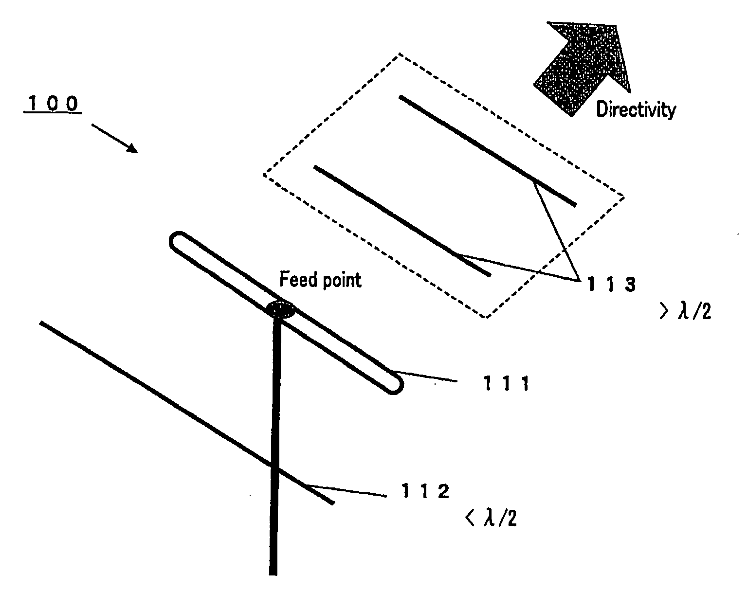
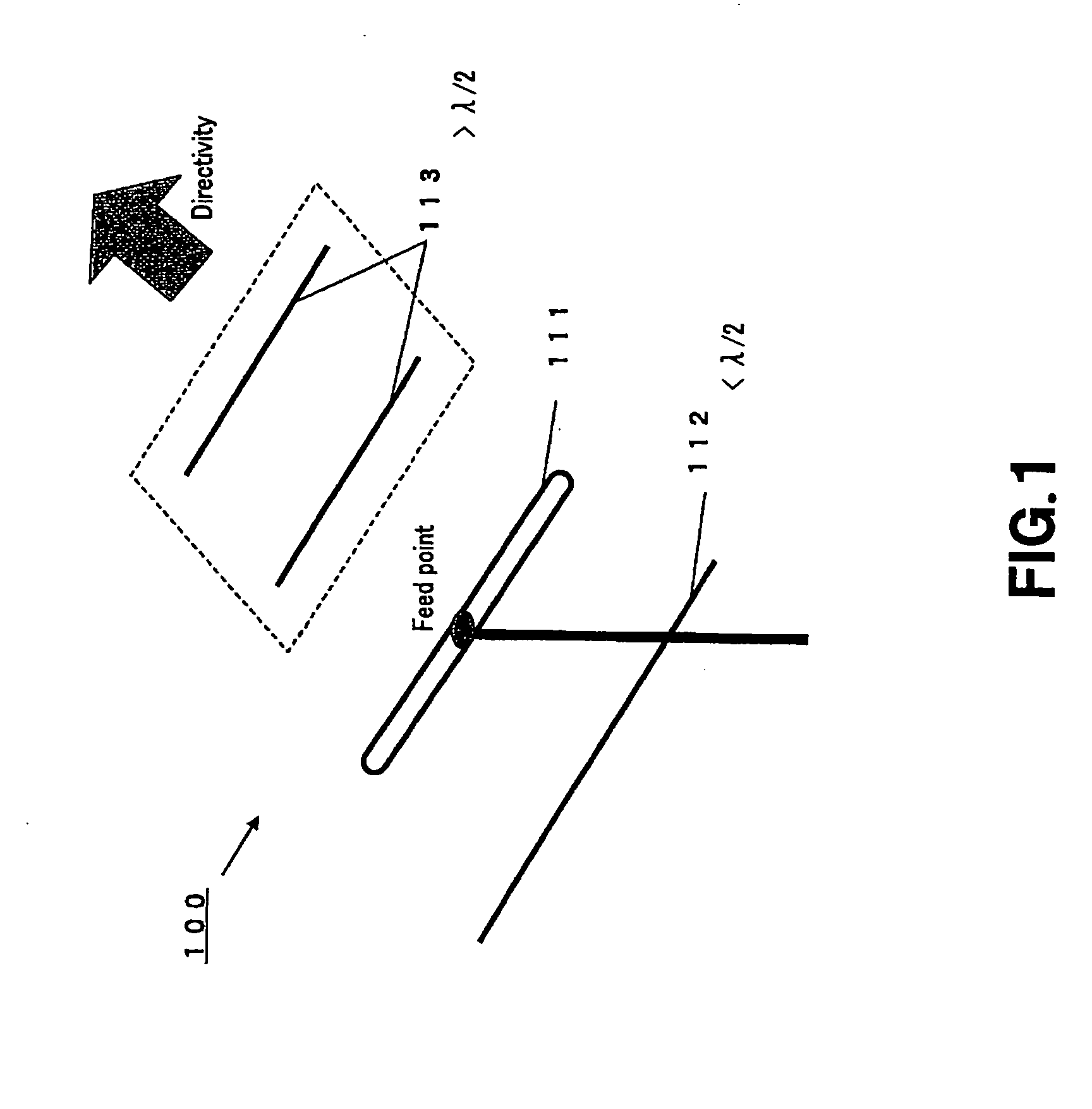
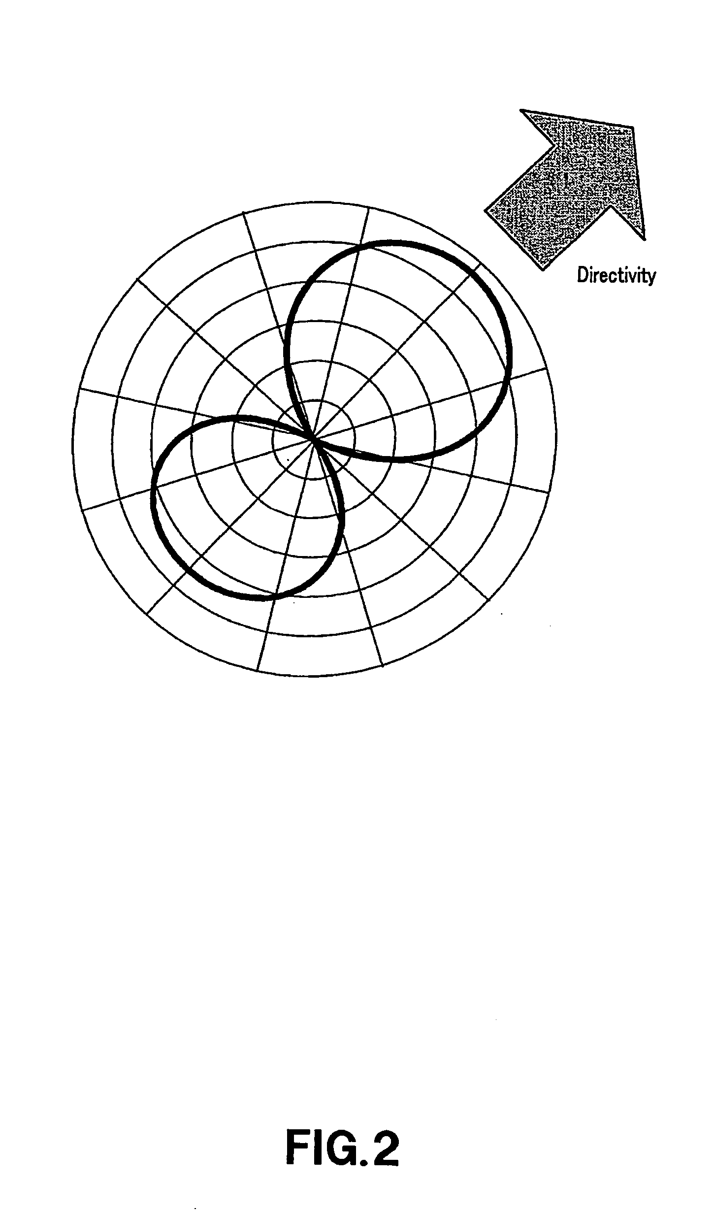
[0046] As shown in FIG. 3A, a multibeam antenna 10 shown in FIG. 3, which is obtained by modifying a Yagi-Uda antenna into a slot configuration, has an antenna element array including one feed element 11 and two parasitic elements 12 and 13. A switching element 20 for switching the electrical lengths of the parasitic elements 12 and 13 is provided as shown in FIGS. 3B and 3C to make the electrical lengths thereof variable, thereby enabling switching of the directivity in two directions.

[0047] A slot antenna is just a slot (usually about ½ wavelength long) in a conductor (ground surface).

[0048] As shown in FIG. 3A, the slot antenna formed on a ground surface 15A of a double-sided printed board 15 is fed by electromagnetic coupling using a microstripline ...


PUM


Abstract

The present invention has been made to reduce the size and thickness of a multibeam antenna capable of switching the directivity in multi directions. The present invention provides a multibeam antenna including an antenna element array including one or more feed element and N (N: natural number) parasitic elements, wherein the electrical length of one or more parasitic elements are made variable.

Description

CROSS REFERENCE TO RELATED APPLICATIONS [0001] The present invention contains subject matter related to Japanese Patent Application JP 2004-244047 filed in Japanese Patent Office on Aug. 24, 2004, the entire contents of which being incorporated herein by reference. BACKGROUND OF THE INVENTION [0002] 1. Field of the Invention [0003] The present invention relates to a multibeam antenna capable of switching the directivity in multi-directions and is suitably used for a micro communication module implementing an information communication function, storage function, and the like, the micro communication module being attached to various electronic devices such as a personal computer, a mobile phone, or an audio device when used. [0004] 2. Description of the Related Art [0005] For example, information such as music, voice, various data, image, or the like becomes easier to handle through the use of a personal computer or mobile device, along with a recently ongoing progress of digitization...

Claims


Application Information

Patent Timeline
Patent Type & Authority Applications(United States)
IPC IPC(8): H01Q13/10H01Q3/44H01Q19/30H01Q21/06
CPCH01Q19/30H01Q13/10H01Q13/106H01Q21/064H01Q25/002
Inventor MORI, KOHEI
Owner SONY CORP
Why Eureka
Try Eureka