Drive control device of motor and disk rotation system

a technology of drive control and control device, which is applied in the direction of record information storage, instruments, electronic commutators, etc., can solve the problems of speeding up involving an increasing the hard disk drive of such a small diameter is likely to generate the irregularities of rotation, so as to reduce the burden on the microprocessor, reduce the rotational irregularities of the motor depending on individual differences, and reduce the effect of rotating irregularities of the motor due to the variations of load

Active Publication Date: 2006-03-02
RENESAS ELECTRONICS CORP
View PDF3 Cites 38 Cited by
  • Summary
  • Abstract
  • Description
  • Claims
  • Application Information

AI Technical Summary

Benefits of technology

[0006] The hard disk drive of such a small diameter is likely to generate the irregularities of rotation, because the inertia of the disk becomes lower and the traveling of a magnetic head is likely to vary the load on the spindle motor. Accordingly, the speed control to suppress the irregularities of rotation becomes necessary for the hard disk drive. Further, the microprocessor performs the control of a voice coil motor, in addition to the speed control of the spindle motor. Therefore, it is expected to relieve the burden on the microprocessor by leaving the speed control of the spindle motor to a motor drive control device (control LSI).
[0017] According to another aspect of the invention, the drive control device performs the initial acceleration by the switching control of the energizing phase based on the detection of the magnetic pole positions of the rotor, with the control loop opened for the speed control. The device performs the acceleration in the range of some % to about 90% of the target rotational speed by the PLL control that brings the zero crossing point of the back electromotive force and the zero point of the output current into coincidence. In regard to the acceleration over 90% of the target speed, the device performs the phase control to put the phase of the coil drive voltage in lead by a predetermined phase against the phase of the back electromotive force based on the back electromotive force of the coil, and the speed control based on the output from the speed error detection circuit and the output from the current output circuit. Thus, the time required until the motor reaches the steady rotational speed is shortened without an increase of the burden on the microprocessor.

Problems solved by technology

However, in the system that a microprocessor performs the speed control of the spindle motor, the speeding-up involves an increasing burden on the microprocessor.
The hard disk drive of such a small diameter is likely to generate the irregularities of rotation, because the inertia of the disk becomes lower and the traveling of a magnetic head is likely to vary the load on the spindle motor.

Method used


Image

  • Drive control device of motor and disk rotation system
  • Drive control device of motor and disk rotation system
  • Drive control device of motor and disk rotation system

Examples


Embodiment Construction

[0034] The preferred embodiments will be described with reference to the accompanying drawings.

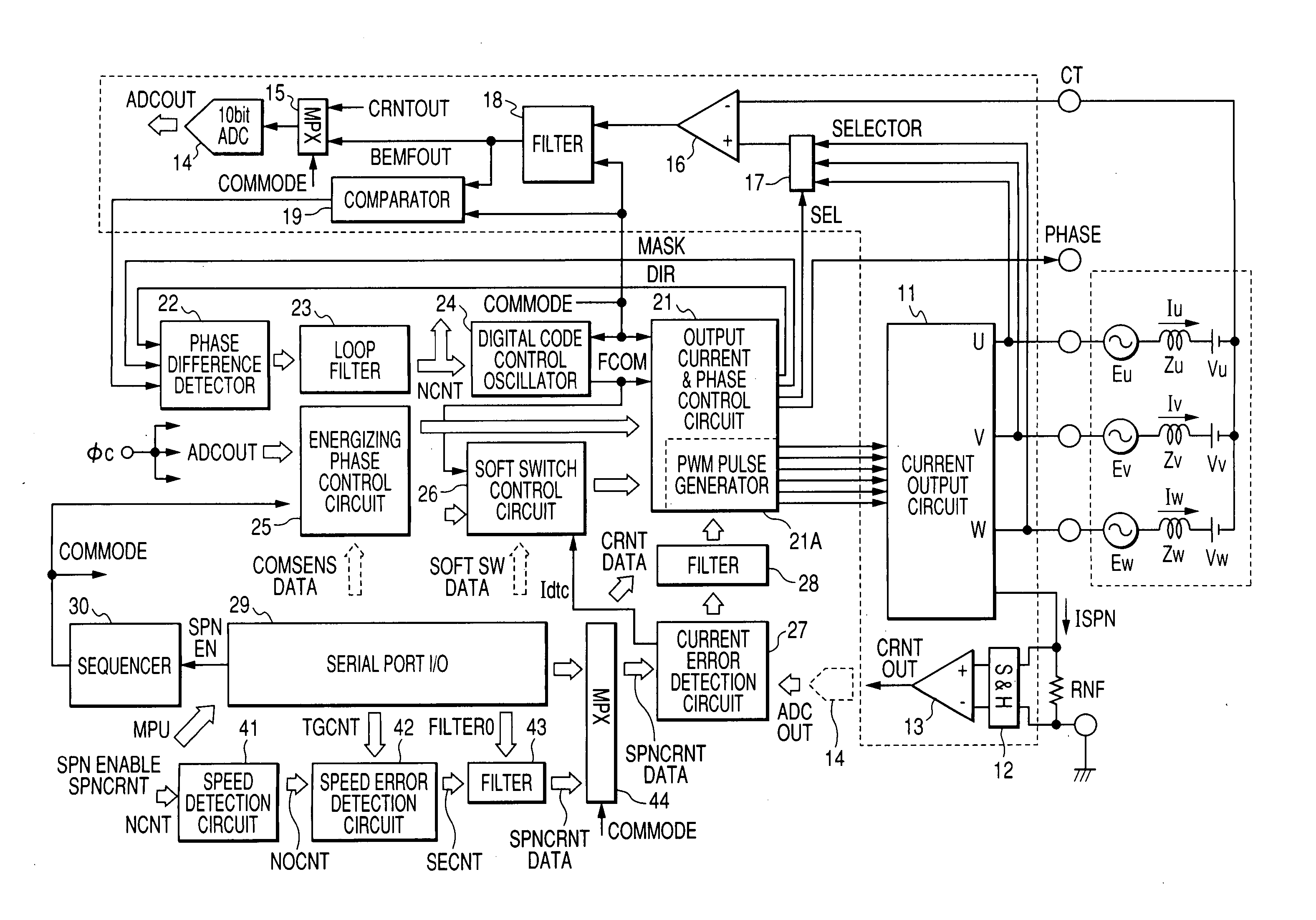
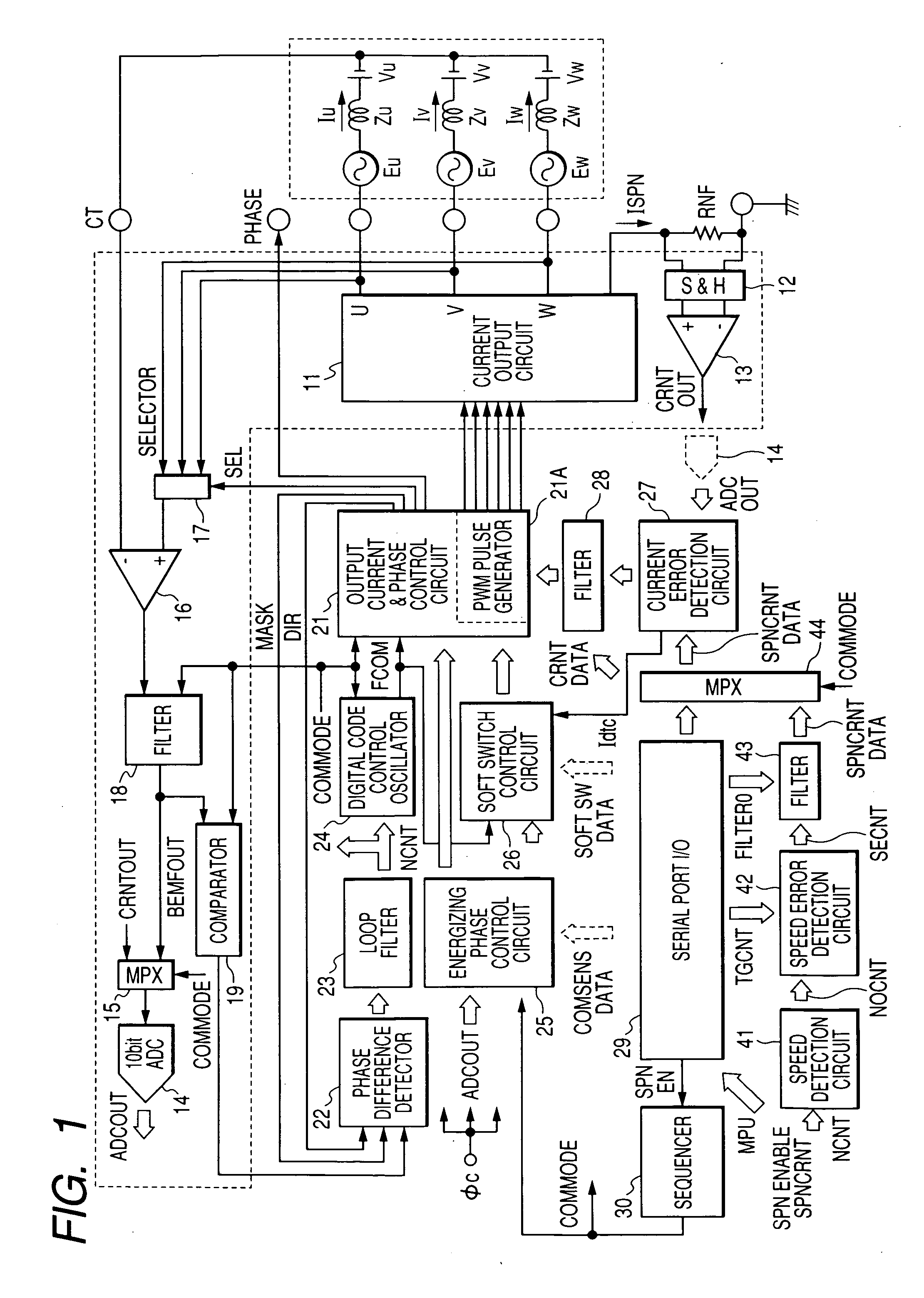
[0035]FIG. 1 illustrates a schematic configuration in which the present invention is applied to a drive control circuit of a three-phase brushless motor used for the spindle motor in a hard disk drive and the like. The circuit illustrated in FIG. 1 is formed on one or several semiconductor substrates of single crystal silicon or the like, except coils Lu, Lv, and Lw of the motor.

[0036] In FIG. 1, a current output circuit 11 sequentially supplies currents to the coils Lu, Lv, and Lw of the three-phase brushless motor. An output current & phase control circuit 21 generates PWM (Pulse Width Modulation) signals for driving output transistors of the current output circuit 11 and controlling output currents, and supplies the PWM signals to the current output circuit 11; and it supplies a selector 17 with a signal SEL for selecting coil terminals that detects back electromotive forces. The symb...


PUM

PropertyMeasurementUnit
mechanical angleaaaaaaaaaa
diameteraaaaaaaaaa
angleaaaaaaaaaa

Abstract

A drive control device of a DC brushless multi-phase motor performs the speed control of the motor in place microprocessor, the burden on the microprocessor is relieved. The drive control device detects a zero crossing point of the back electromotive force in the non-energizing phase to perform the energizing switching to the coils by the PLL control, and includes a current detection circuit that detects currents flowing through the coils to perform the speed control of the motor based on the detected currents. The drive control device also, compares outputs from speed error detection circuit with outputs from the current detection circuit to determine the currents to be made to flow through the coils, and thereby controls the current output circuit.

Description

CROSS REFERENCE TO RELATED APPLICATION [0001] The present application claims priority from Japanese patent application No. 2004-251748 filed on Aug. 31, 2004, the contents of which is hereby incorporated by reference into this application. BACKGROUND OF THE INVENTION [0002] The present invention relates to a drive control system of a brushless motor and a technique effective in use for the speed control of the motor. As an example, it relates to a technique effective in application to a semiconductor integrated circuit for driving and controlling a spindle motor that drives to rotate a disk storage medium such as a magnetic disk of a hard disk drive, and a motor drive control device using the integrated circuit. [0003] The hard disk drive generally uses a DC brushless multi-phase motor as the so-called spindle motor. The hard disk drive rotates a magnetic disk at a high speed by means of the spindle motor, brings a read / write magnetic head close to the surface of the rotating magnet...

Claims


Application Information

Patent Timeline
Patent Type & Authority Applications(United States)
IPC IPC(8): G11B15/46H02P6/18H02P6/06H02P6/08H02P6/182
CPCG11B19/28
Inventor ITAGAKI, KICHIYASATO, HIROSHIYOSHIDA, KENJI
Owner RENESAS ELECTRONICS CORP
Why Eureka
Try Eureka