Sensor-equipped wheel support bearing assembly

a technology of axial load and bearing assembly, which is applied in the direction of instruments, galvano-magnetic hall-effect devices, force/torque/work measurement apparatus, etc., can solve the problem of prior art leaving a durability problem unsolved, the use of the number of wheel revolutions is still insufficient, and the axial load acting on the vehicle wheel can be measured more accurately. , the effect of high resolving power

Inactive Publication Date: 2006-03-02
NTN CORP
View PDF12 Cites 20 Cited by
  • Summary
  • Abstract
  • Description
  • Claims
  • Application Information

AI Technical Summary

Benefits of technology

[0012] According to the present invention, since the rotation sensor is positioned between the displacement sensors that are disposed at respective locations circumferentially equidistantly spaced from each other, the rotation sensor can be disposed at any desired position between the displacement sensors in the circumferential direction and the sensors can be arranged in compact in the bearing assembly even in the case where care is required to avoid an undesirable interference between a wiring lead-out port of the rotation sensor and the knuckle. Also, since the cylindrical extension is used as a to-be-detected member cooperable with the displacement sensors, the displacement of the inner member can be amplified to increase the measuring sensitivity, making it possible to measure the axial load acting on the vehicle wheel more ac...

Problems solved by technology

However, the use of the number of wheel revolutions is still insufficient and, therefore, it is desired to make use of one or more additional sensors so that the automotive vehicle can be controlled for an improved safety.
However, no space for installation of the load sensor for detecting the load acting on the respective vehicle wheel is available and, therefore, the attitude control through the detection of the load can hardly be realized.
How...

Method used


Image

  • Sensor-equipped wheel support bearing assembly
  • Sensor-equipped wheel support bearing assembly
  • Sensor-equipped wheel support bearing assembly

Examples


Embodiment Construction

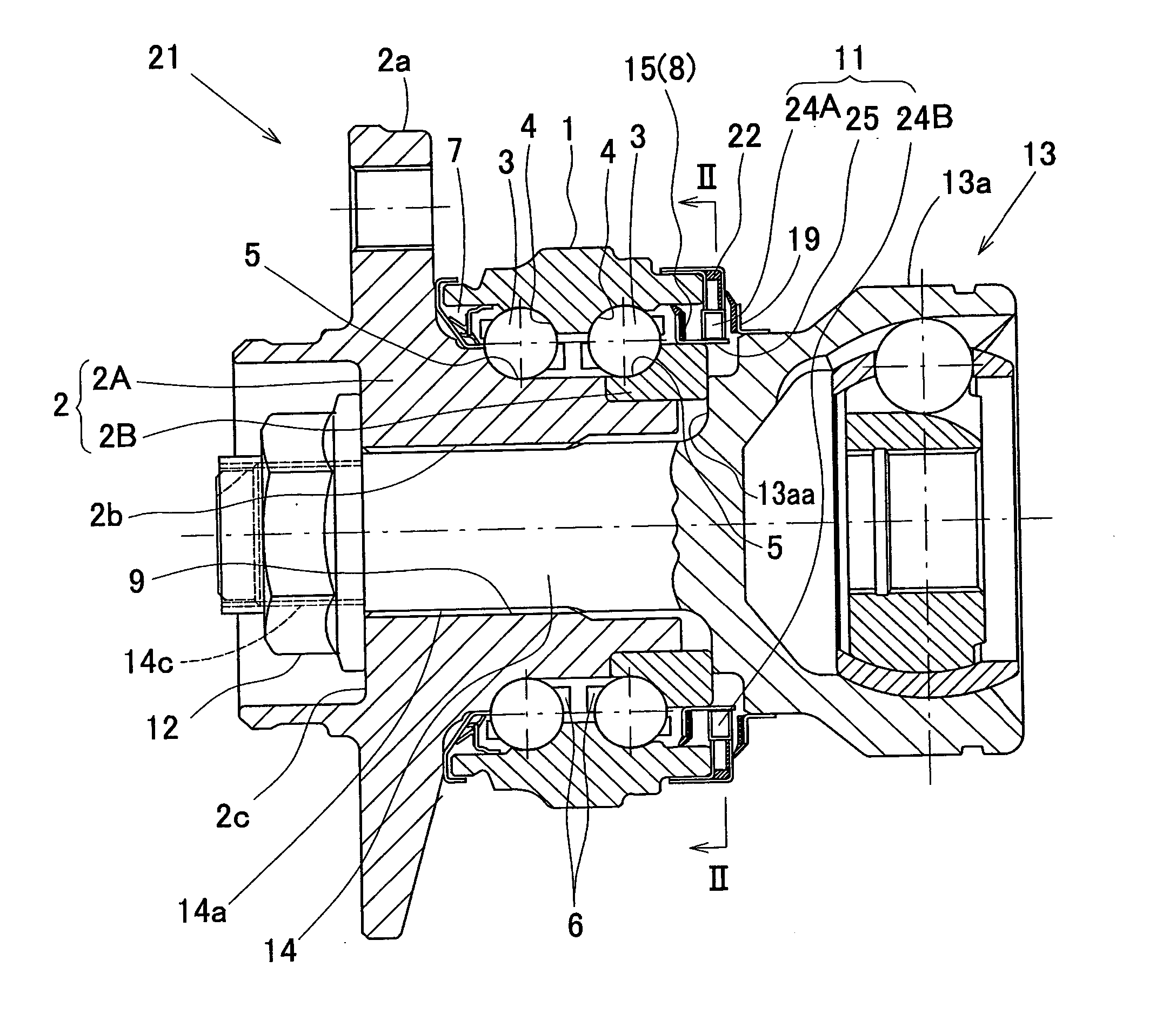
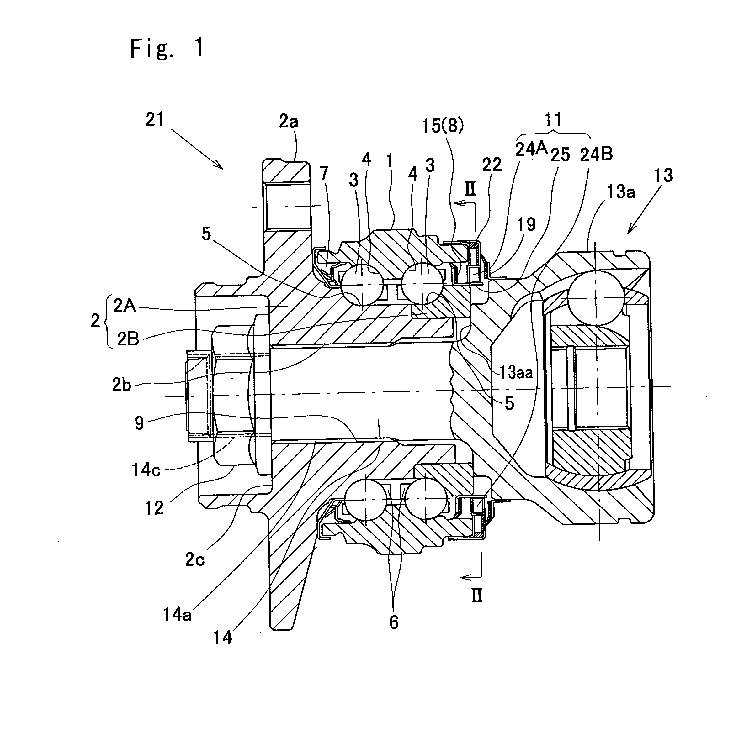
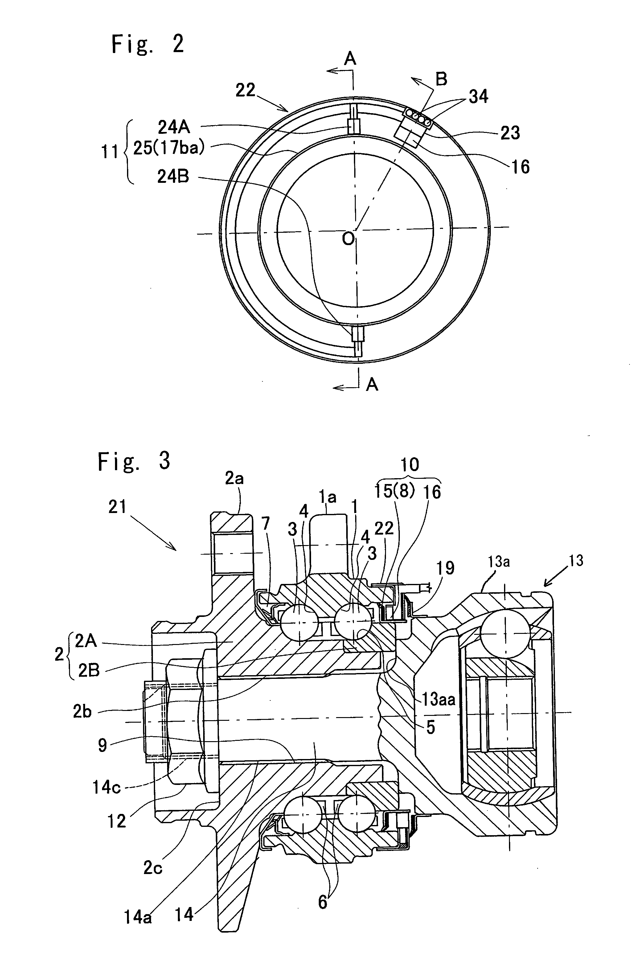
[0024] A preferred embodiment of the present invention will now be described with particular reference to the accompanying drawings, particularly to FIGS. 1 to 7. A wheel support bearing assembly according to this embodiment is an inner race rotating model of a third generation type and is shown as applied for supporting a drive wheel of an automotive vehicle. It is to be noted that the terms, “outboard” and “inboard”, hereinabove and hereinafter used in this specification, are intended to represent the sides facing the outside and inside of the vehicle, respectively. So far shown in FIG. 1, left and right portions of the drawing sheet represent outboard and inboard sides, respectively.

[0025] Referring to FIG. 1, the wheel support bearing assembly has a bearing 21 including an outer member 1 having an inner peripheral surface formed with a plurality of axially spaced inboard and outboard raceway surfaces 4, an inner member 2 positioned inside the outer member 1 and having an outer ...


PUM


Abstract

A rotation sensor assembly (10) includes an encoder (15), mounted on one end of an inner member (2) of a bearing (21), and a rotation sensor (16) fitted to one end of an outer member (1) of the bearing (21) in face-to-face relation with the encoder (15). A cylindrical wall (17b) of a core metal (17) of the encoder (15) press-fitted onto the inner member (2) has a cylindrical extension (17ba) protruding axially outwardly from one end of the cylindrical wall (17b). A displacement sensor assembly (11) includes a pair of displacement sensors (24) provided in face-to-face relation with the cylindrical extension (17ba) and spaced an equidistantly from each other in a circumferential direction. The rotation sensor (16) is positioned between the displacement sensors (24) in the circumferential direction.

Description

BACKGROUND OF THE INVENTION [0001] 1. Field of the Invention [0002] The present invention relates to a sensor-equipped wheel support bearing assembly having a displacement sensor for detecting a load imposed on a bearing and a rotation sensor for detecting the number of revolution of a wheel, both built therein. [0003] 2. Description of the Prior Art [0004] For stabilized run of an automotive vehicle, it is known to provide a wheel support bearing assembly with a rotation sensor for detecting the number of revolution of each of vehicle wheels. In this type of wheel support bearing assembly, the use has been suggested in, for example, the Japanese Laid-open Patent Publication 2003-336652, of sensors, for example, a temperature sensor and a vibration sensor so that in addition to the number of revolutions, vehicle operating conditions useful to the stabilized run of the automotive vehicle can be detected. [0005] To assure a cruising safety of an automotive vehicle in general, the numb...

Claims


Application Information

Patent Timeline
IPC IPC(8): F16C19/00
CPCB60G2204/115B60G2400/208B60G2400/64F16C19/522F16C33/78G01P3/487F16C2326/02G01B7/144G01L5/0023G01P3/443F16C41/007F16C19/186
Inventor IWAMOTO, KENICHIYAMAMOTO, KEN
Owner NTN CORP
Why Eureka
Try Eureka