Multiple-axis cutting toroidal end mill

a toroidal end mill and multi-axis technology, applied in the field of single-piece toroidal end mills, can solve the problems of increasing tool cost, not being practicable in all applications, and many of the machine tools currently in use, so as to improve the effective machining of machines, reduce horsepower and torque capabilities, and increase the removal rate of cubic inches.

Inactive Publication Date: 2006-03-02
BERKSHIRE PRECISION TOOL
View PDF11 Cites 38 Cited by
  • Summary
  • Abstract
  • Description
  • Claims
  • Application Information

AI Technical Summary

Benefits of technology

[0011] The present invention provides several advantages over prior art end mills with or without inserts. First, it is our experience that the present invention end mill increases the effective machining of machines with lower horsepower and torque capabilities. Such machines can achieve typically higher cubic inch removal rate per minute of operation with the present invention than they could achieve using a conventional end mill or insert standard tool. The higher cubic inch removal rates are achieved with light depth of cut (e.g., 80% of radius on toroidal end mill, for depth of cut) at high feeds rates per tooth or flute.
[0012] It is our further experience that accelerated speeds and feeds greater than that conventionally used for a given material, with shallow depth of cut, are possible with the present invention end mill. With the present invention solid design end mill, material specific end mills can be produced and remanufactured to meet the manufacturing needs without costly retooling. Such material specific end mills can be used to mill soft pre-hard and hardened die / steels, cast steels, cast iron, all stainless steels, nickel and titanium alloys, graphite and more. The present invention end mills can also be readily manufactured in forms having more than two flutes, thereby further increasing the feed rates possible with the tool.
[0013] The present invention toroidal end mill provides the following additional advantages: 1) increased insert shock value; 2) improved tolerance build-up relative to end mills utilizing inserts; 3) a more uniform end mill, that facilitates operator control in the machining of a part; 4) no inserts to lose and damage the tool holder and the machined part; 5) an end mill that can be resharpened; 6) an end mill that does not have a location along the cutting edge, center or side, where the velocity is zero during any cutting process; 7) an end mill that produces a desirable surface finish; 8) an end mill that can perform in a helical interpolation (cutting in three axes X, Y and Z at the same time) with no zero surface feet-per-minute causing toll failure; 9) an end mill with a cutting surface that creates a positive shear action in cutting of materials; 10) an end mill that can be manufactured with a cutting diameter that is so small that it is not practically attainable by an end mill utilizing inserts; 11) an end mill that can be indexed from flute to flute to decrease harmonic responses; and 12) an end mill that can be readily shaped to a variety of different configurations, including geometries not practically possible with inserts.

Problems solved by technology

Many cutting tool companies are bringing tools to market that, though very productive in theory, are often not practical in all applications and environments given the horsepower, torque, or rigidity restrictions required to properly utilize their geometries.
Many of the machine tools currently in use, do not have the horsepower or torque capabilities required by these milling tools.
End mills with carbide inserts have several drawbacks, including: 1) increased tool cost; 2) potential for relative movement between an insert and the tool holder during the machining process, which can degrade the ability of the tool to hold specifications; 3) they typically have a negative rake angle that can undesirably plow work piece material during the machining process; 4) they typically have a shock value in machining that is less than a solid tool, and are therefore more susceptible to damage (e.g., inserts often break and dislodge from the tool holder, thereby possibly destroying the tool holder and damaging the part); 5) increased undesirable tolerance build-up; and 6) practical limitations regarding how small the diameter can be using inserts.
These ball nosed end mills have disadvantages as well.
In addition, when a ball mill is cutting material in a side movement the center drags, or when operating in a plugging or inward movement, the center of the ball mill comes under extreme force.
Ball mills also often leave a less than desirable surface finish.

Method used


Image

  • Multiple-axis cutting toroidal end mill
  • Multiple-axis cutting toroidal end mill
  • Multiple-axis cutting toroidal end mill

Examples


Embodiment Construction

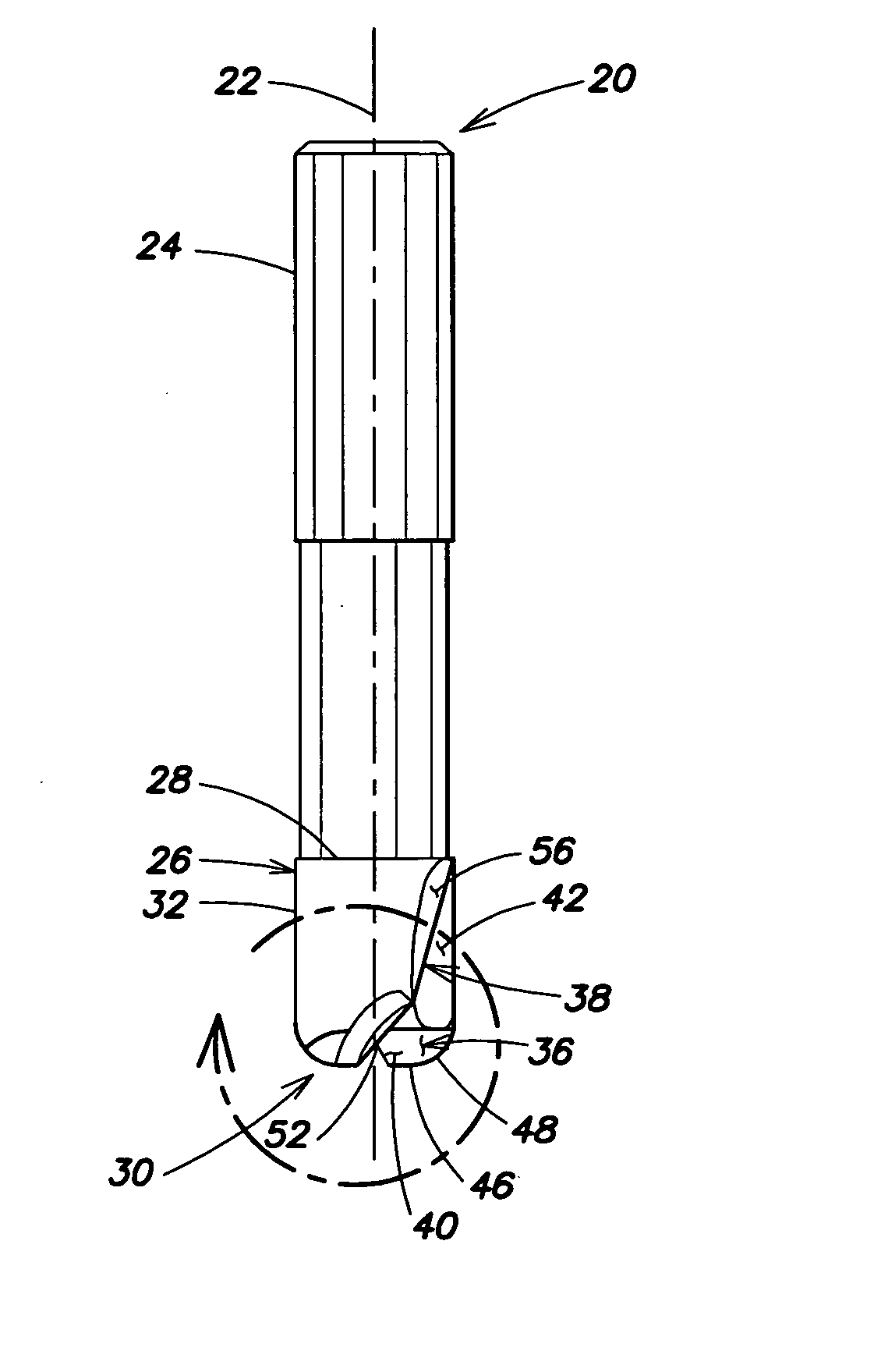
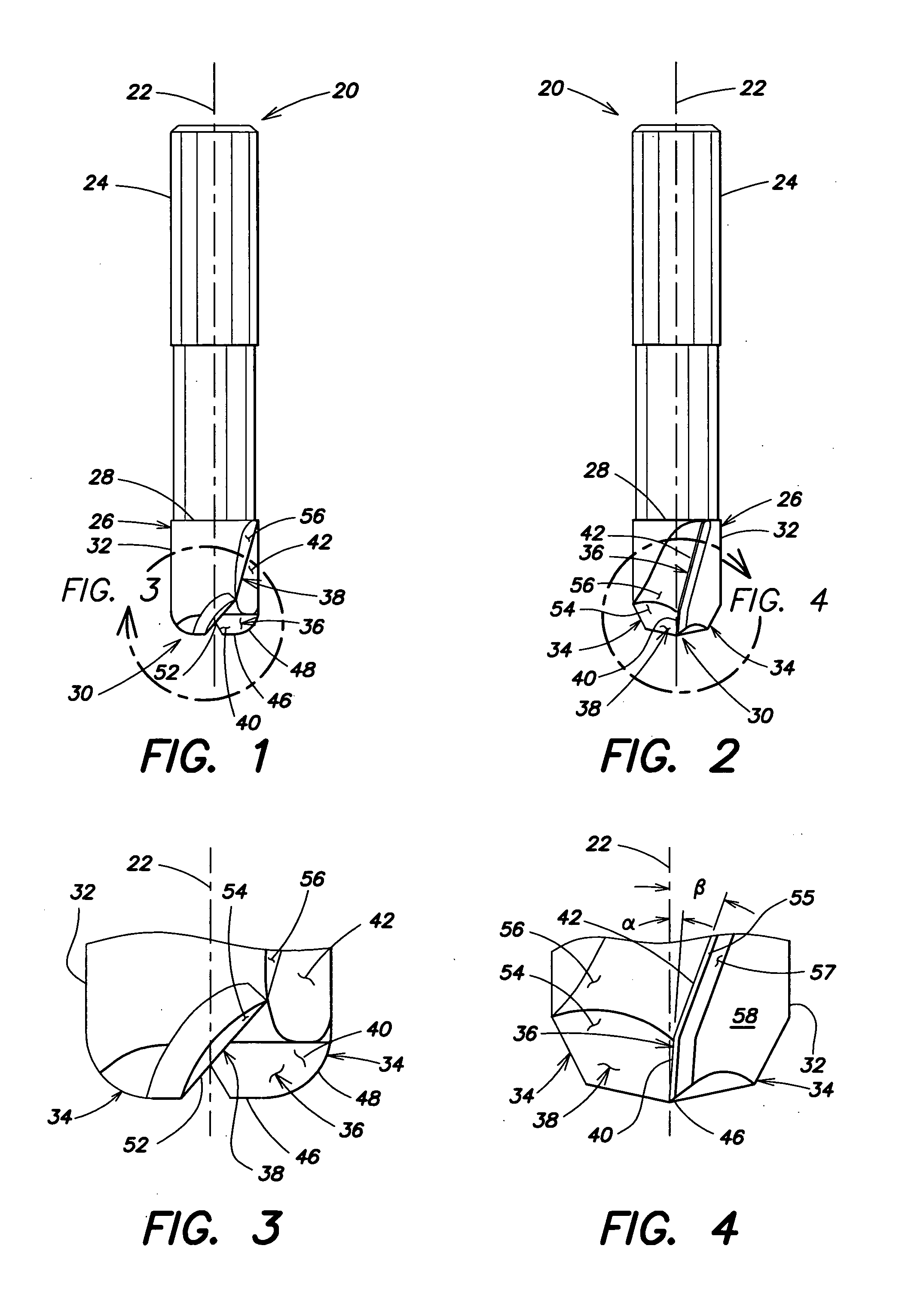
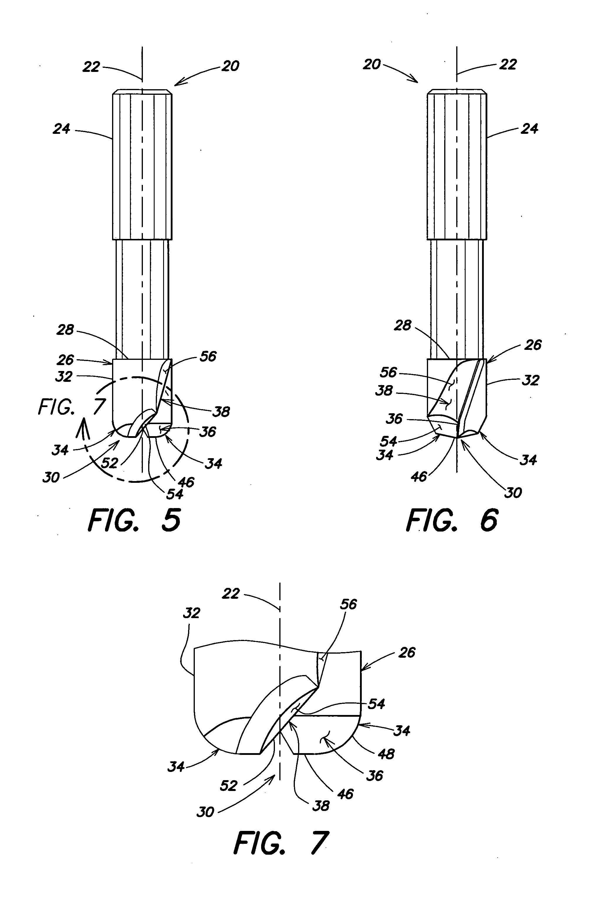
[0029] Referring to FIGS. 1-14, a one-piece toroidal end mill 20 having an axis of rotation 22 is provided. The end mill 20 includes a shank section 24 and a fluted section 26. The shank section 24 extends along the axis of rotation 22. The fluted section 26 extends along the axis of rotation 22, and has a first end 28 integrally attached to the shank section 24, a second end 30 (also referred to as the “tip”) opposite the first end 28, and an outer surface 32. The fluted section 26 includes a plurality of teeth 34. FIGS. 1-14 show embodiments of the present invention end mill 20 having a pair of teeth 34. Alternative embodiments may include more than two teeth 34. Each of the teeth 34 has a cutting surface 36 and a shoulder surface 38.

[0030] The cutting surface 36 extends from the tip 30 toward the shank section 24, between and contiguous with the shoulder surface 38 and the outer surface 32. In some embodiments, the cutting surface is disposed in one plane. For example, FIGS. 5-7...


PUM


Abstract

A one-piece toroidal end mill having an axis of rotation is provided. The end mill includes a shank section and a fluted section. The shank section extends along the axis of rotation. The fluted section extends along the axis of rotation, and has a first end, an outer surface, and a plurality of teeth. The first end is integrally attached to the shank section. Each of the plurality of teeth has a cutting surface and a shoulder surface. The cutting surface includes a cutting edge. The shoulder surfaces intersect with one another to form a center void disposed between the cutting surfaces.

Description

[0001] This application claims the benefit of and incorporates by reference essential subject matter disclosed in U.S. Provisional Patent Application No. 60 / 606,316 filed on Sep. 1, 2004.BACKGROUND OF THE INVENTION [0002] 1. Technical Field [0003] The present invention relates to end mills in general, and to single piece toroidal end mills in particular. [0004] 2. Background Information [0005] There is a need for an effective alternative to current products that can utilize the rotational speeds and feed rates of modern machine tools in a production environment. Every machine shop is looking for ways to maximize its productivity within the operating parameters of its machine tools. Many cutting tool companies are bringing tools to market that, though very productive in theory, are often not practical in all applications and environments given the horsepower, torque, or rigidity restrictions required to properly utilize their geometries. Many of the machine tools currently in use, do...

Claims


Application Information

Patent Timeline
Patent Type & Authority Applications(United States)
IPC IPC(8): B23C5/10
CPCB23C5/10B23C5/1009B23C2210/0407Y10T407/1948B23C2210/084B23C2210/54B23C2210/045
Inventor FLYNN, CLIFFORD M.MOSER, LOUIS A.LIEDES, JYRKI T.
Owner BERKSHIRE PRECISION TOOL
Why Eureka
Try Eureka