Method for examining corrosion of a steel reinforcement rod embedded in concrete

a technology of reinforcement rods and concrete, applied in the field of methods for examining reinforcement steels, can solve the problems of increasing errors, difficult on-the-spot examination, and methods according to the prior arts that do not meet the requirements of actual use, and achieves strong corrosion sustainability, improved examination accuracy, and high sensibility

Inactive Publication Date: 2006-03-09
NAT CENT UNIV
View PDF1 Cites 16 Cited by
  • Summary
  • Abstract
  • Description
  • Claims
  • Application Information

AI Technical Summary

Benefits of technology

[0005] Therefore, the main purpose of the present invention is to be widely applied to examine the status of the corrosion on a reinforcement steel in a construction in a long term. In addition, the corrosion speed of the reinforcement steel detected can be a base for evaluating the safety of the construction.
[0006] Another purpose of the present invention is to obtain high sensibility, strong corrosion sustainability and electromagnetic jam prevention for improving the accuracy of the examination.
[0012] By doing so, the present invention obtains high sensibility, strong corrosion sustainability and electromagnetic jam prevention for improving the accuracy of the examination and can be widely applied to examine the status of the corrosion on a reinforcement steel in a long term.

Problems solved by technology

Moreover, for example, if a potential detection is used (based on ASTM-C876, the most common method used in this kind of business) and the original corrosion potential detected is under −350 mV, the potential detected may become −150 mV under the influence of the process of carbonization so that erroneous judgments may be increased and an on-the-spot examination may become harder.
Consequently, the methods according to the prior arts do not fulfill all the requirements on actual use.

Method used


Image

  • Method for examining corrosion of a steel reinforcement rod embedded in concrete
  • Method for examining corrosion of a steel reinforcement rod embedded in concrete
  • Method for examining corrosion of a steel reinforcement rod embedded in concrete

Examples


Embodiment Construction

[0016] The following descriptions of the preferred embodiments are provided to understand the features and the structures of the present invention.

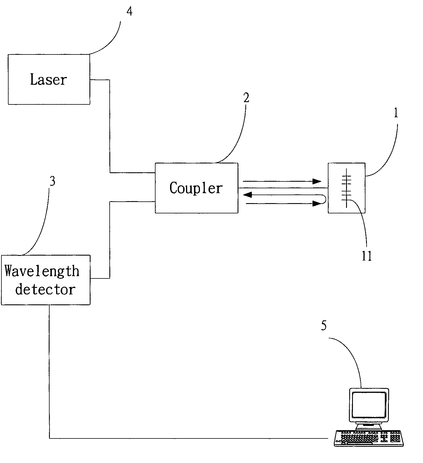
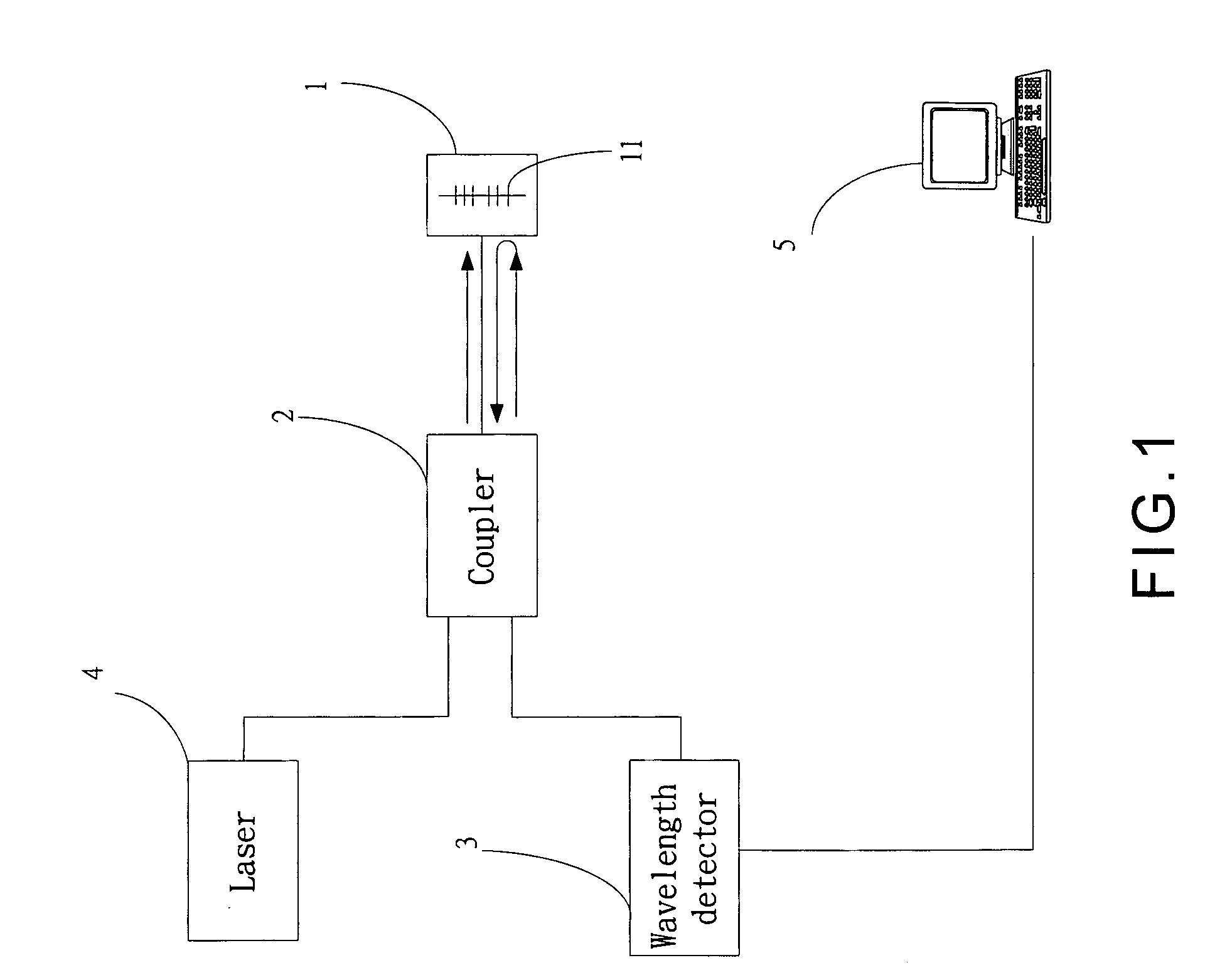
[0017] Please refer to FIG. 1, which is a system view according to the present invention. As shown in the figure, the present invention is a system comprising a sensor 1, a coupler 2, a wavelength detector 3, a laser 4 and an analyzer.

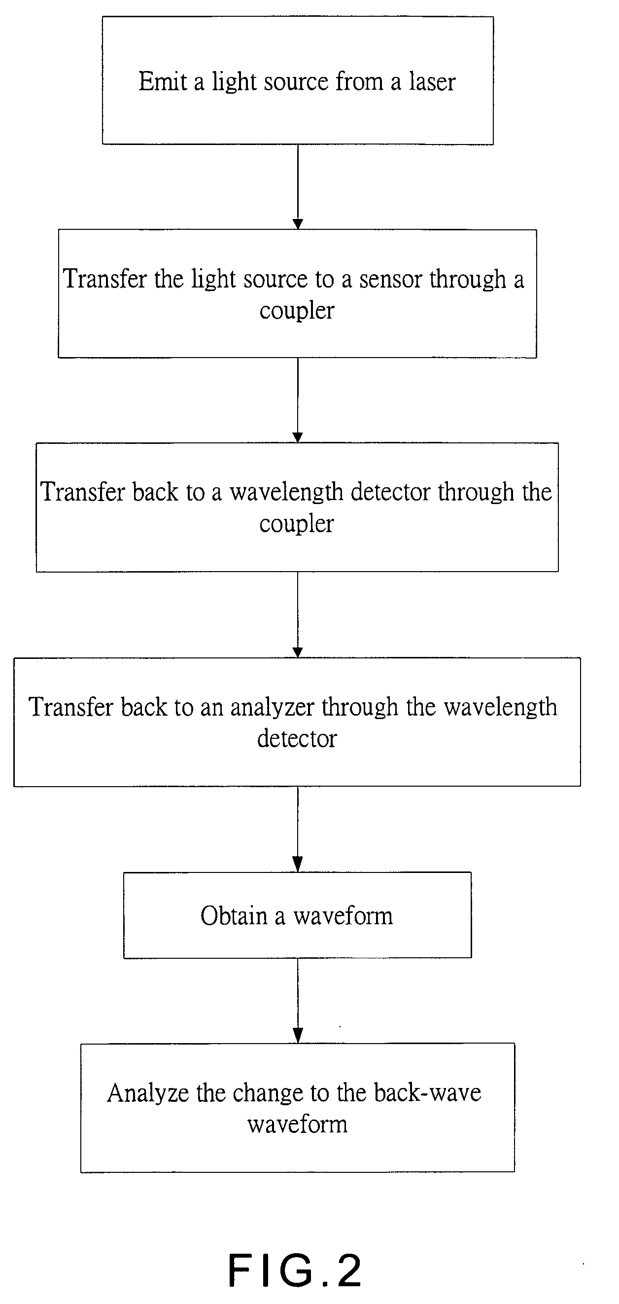
[0018] A method for examining the corrosion of a reinforcement steel by using the above system comprises the following steps: [0019] i. Obtain a sensor 1 having a fiber Bragg grating 11, which can be a round bushing or a clamper. [0020] ii. Connect a coupler 2 to the sensor 1 under a proper protection, which can be a one-to-two coupler. [0021] iii. Depose the sensor 1 at a proper position on a reinforcement steel. [0022] iv. Connect a laser 4 and an analyzer 5 to the coupler 2, and depose a wavelength detector 3 between the coupler 2 and the analyzer 5 so that, according to the present invention, examinati...


PUM

PropertyMeasurementUnit
corrosion potentialaaaaaaaaaa
corrosionaaaaaaaaaa

Abstract

The present invention is a method for examining corrosion on a reinforcement steel. A sensor with a fiber Bragg grating is connected with a coupler; and the coupler is connected with a laser and an analyzer. Apply the sensor at a proper position on the reinforcement steel. A light source of the laser goes to the sensor through the coupler; and then the light passes the sensor and is transferred back to the analyzer. The analyzer can then figure out the strain out of the deformation and swell on the reinforcement steel owing to its corrosion by detecting the drift of the Bragg wavelength of the light. By doing so, the present invention obtains high sensitivity, strong corrosion sustainability and electromagnetic jam prevention so that the accuracy of the detection becomes higher and it can be widely applied to examine the corrosion on the reinforcement steel in a long term.

Description

FIELD OF THE INVENTION [0001] The present invention relates to a method for examining a reinforcement steel; more particularly, relates to a method for examining the trend of the corrosion of a reinforcement steel with high sensitivity, strong corrosion sustainability and electromagnetic jam prevention under a long-term monitoring. DESCRIPTION OF THE RELATED ARTS [0002] Nowadays, common methods for examining the corrosion of a reinforcement steel embedded in a concrete are potential detection, DC linear polarization and AC impedance method. [0003] The above three methods are all related to conductivity and potential. Yet, when the chloride ion in the concrete surrounding the reinforcement steel increases or the concrete is in a process of carbonization or the concrete is with porosity, the potential or the resistance detected will be apparently influenced by them. It is because the chloride ion will increase conductivity; the process of carbonization may produce a potential for the ...

Claims


Application Information

Patent Timeline
Patent Type & Authority Applications(United States)
IPC IPC(8): G01J1/04
CPCG01M11/083G01B11/18
Inventor WANG, CHUNG-YUEPENG, PENG-CHING
Owner NAT CENT UNIV
Why Eureka
Try Eureka