Digital pulse-width-modulation generator

a generator and digital technology, applied in the field of digital pulse width modulation generators, can solve the problems of linearity, efficiency, linearity and efficiency of power available, diaphragm mass, etc., and achieve the effects of reducing the number of individual transducers, reducing cost and manufacturing complexity, and reducing the number of transducers required

Inactive Publication Date: 2006-03-09
YAMAHA CORP
View PDF34 Cites 49 Cited by
  • Summary
  • Abstract
  • Description
  • Claims
  • Application Information

AI Technical Summary

Benefits of technology

[0017] According to a first aspect of the present invention, there is provided a loudspeaker comprising a number of substantially identical transducers, each arranged to convert an electrical loudspeaker input signal into an acoustic output, wherein each transducer is driveable independently of all the others by discreet-time-sampled signals representative of the sounds to be produced by the loud speaker further comprising digital interpolation means to raise the sampling rate of the input signals, pulse amplifiers to raise digital signal levels to a power level adequate to produce the output sound power, and delay means capable of independently delaying the signal to an associated transducer.

Problems solved by technology

The inherent limitations of such analogue loudspeakers are related to: the stiffness of the diaphragms used, the mass of the diaphragms, the linearity and efficiency of and power available from electromechanical motors with adequate bandwidth and limitations on the throw of the diaphragm.
These and other factors combine to cause the analogue loudspeaker to operate with low efficiency and relatively high distortion levels.
With the current prevalence of high quality digital audio material available, frequently in 16-bit binary format with an inherent distortion level of close to 0.002%, it is clear that analogue hi-fidelity loudspeaker systems operating close to the 1% distortion level (500 times worse) are now the limiting factor in audio quality when listening to reproduced sound (including radio, television, compact discs (CD), and digital tape).
The DACs themselves produce further noise and distortion that adds to that already present in the system, and also add extra cost.
As the device relies on the linearity of the transducer, this system has all of the disadvantages of analogue loudspeakers plus some extra ones related to the PWM conversion process, and so is really a digital amplifier technology, not a digital loudspeaker technology.
This causes serious technical problems in practice.
Because of the necessarily mechanical nature of sound producing devices (sound is a mechanical movement of air) this wide dynamic range imposes serious design constraints on the types of devices used for LSB and MSB transducers, and thus makes matching of the devices very difficult—the problems are much worse when one considers a more realistic 10 or 12 bit system where the ratios in power levels between the MSB and LSB transducers are then of the order of 250 to 1000 times, and for a 16-bit system the ratio rises to greater than 16000.
In a binary-weighted transducer (or transducer-array) system, there are serious transient problems caused at points where the code changes from a value with many consecutive low order zeroes or ones to the next level (up or down) where there are many consecutive low order ones or zeroes.
Other such ones-to-zeroes and zeroes-to-ones transitions occur throughout the signal amplitude range, and become more of a problem as the total number of bits increases, as the power of the transient increases relative to the system's least significant bit power level.
Thus, increasing the resolution of the system by adding more bits makes the problem worse, not better.
In addition to the switching transient problem outlined above, there is also a level error associated with such zeroes-to-ones and ones-to-zeroes code changes.
This is because in a real system the transducers cannot easily be matched precisely enough that the most significant bit transducer is precisely one least significant bit greater in effective power or amplitude than the sum of all the lesser-bit transducers acting in concert.
Such unavoidable errors can in practice easily dominate the accuracy of the system and quite independently of the transient effects described above can lead to large distortion components.
In a binary weighted transducer or transducer-array system (as described in U.S. Pat. No. 4,515,997 which does not address this problem either), only extreme mechanical precision can eliminate this problem even in principle, which will inevitably lead to high manufacturing costs even if the precision required is achievable.
In practice, the transducers will necessarily be spatially separated and the matching problems at such transition points then become intractable.
In a 16-bit system, compatible with current digital audio standards, it is highly unlikely that the necessary precision could be achieved at any cost.
Another problem not adequately addressed by existing digital loudspeaker designs is that of transducer dynamics and appropriate drive waveforms for producing the desired acoustic sound output waveform.
This is almost never the case in practice and leads to serious distortion in the generated acoustic waveform.
However, as the word unit is easily confused in this unfamiliar role with its more conventional meaning, we use the phrase unary digit.

Method used


Image

  • Digital pulse-width-modulation generator
  • Digital pulse-width-modulation generator
  • Digital pulse-width-modulation generator

Examples


Embodiment Construction

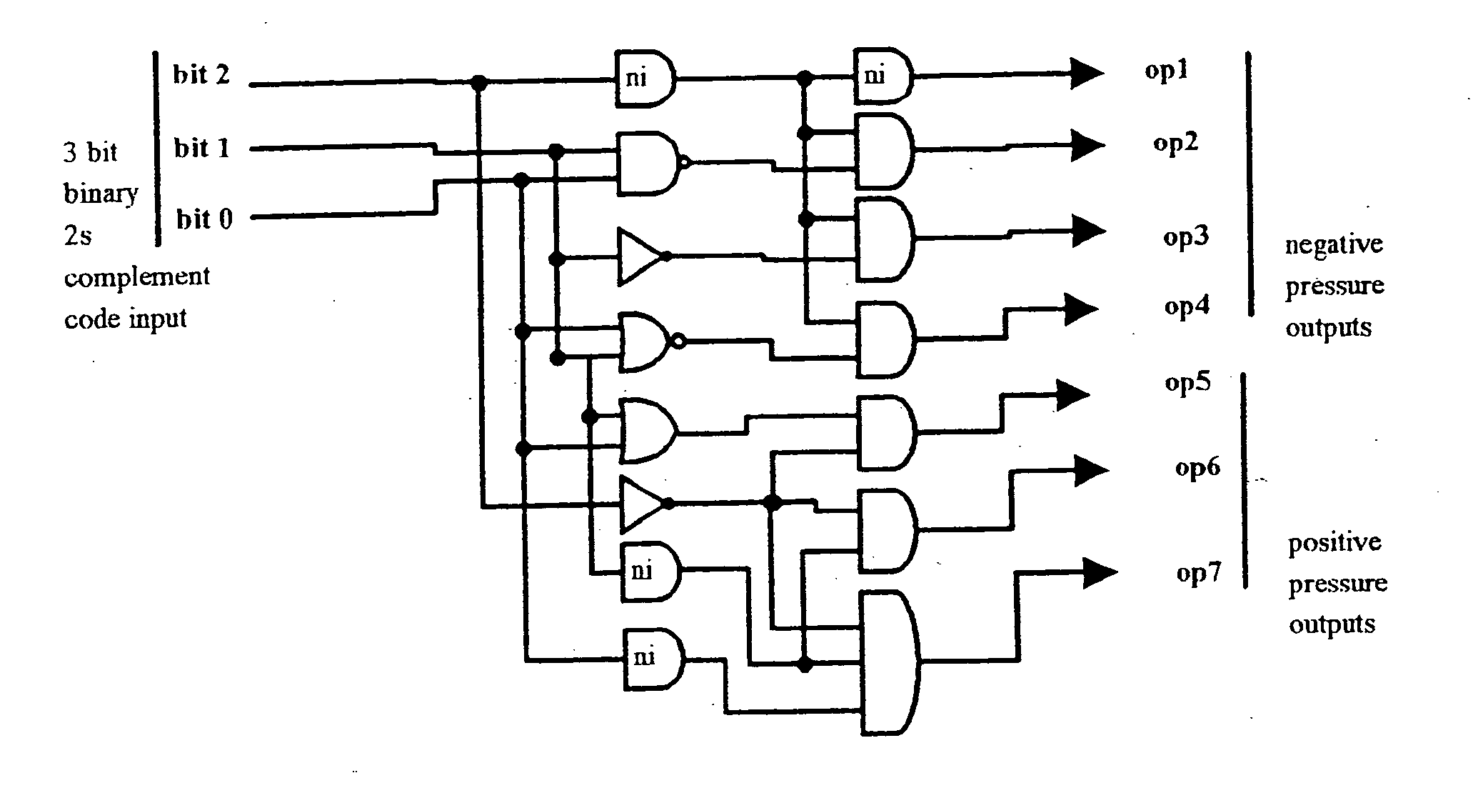
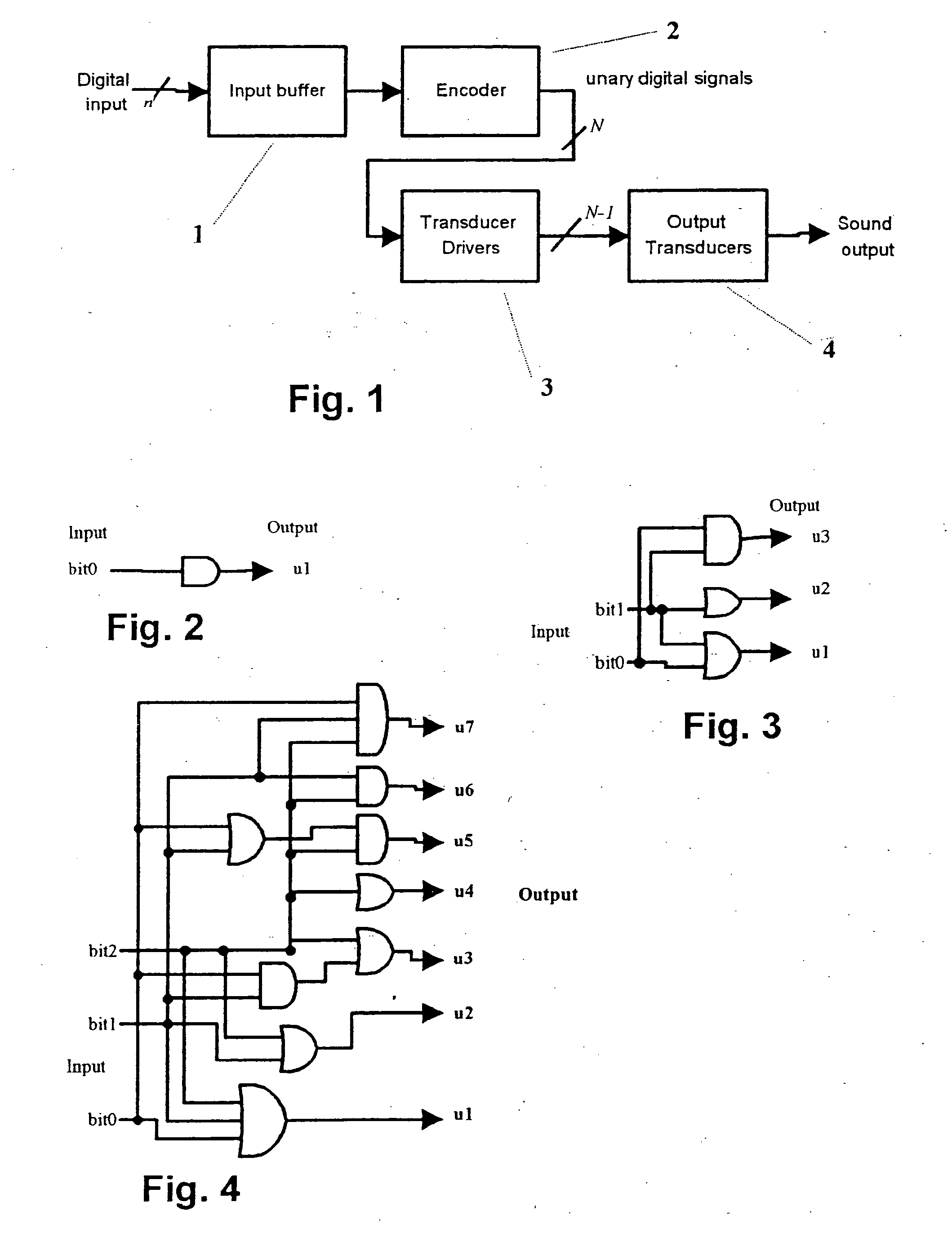
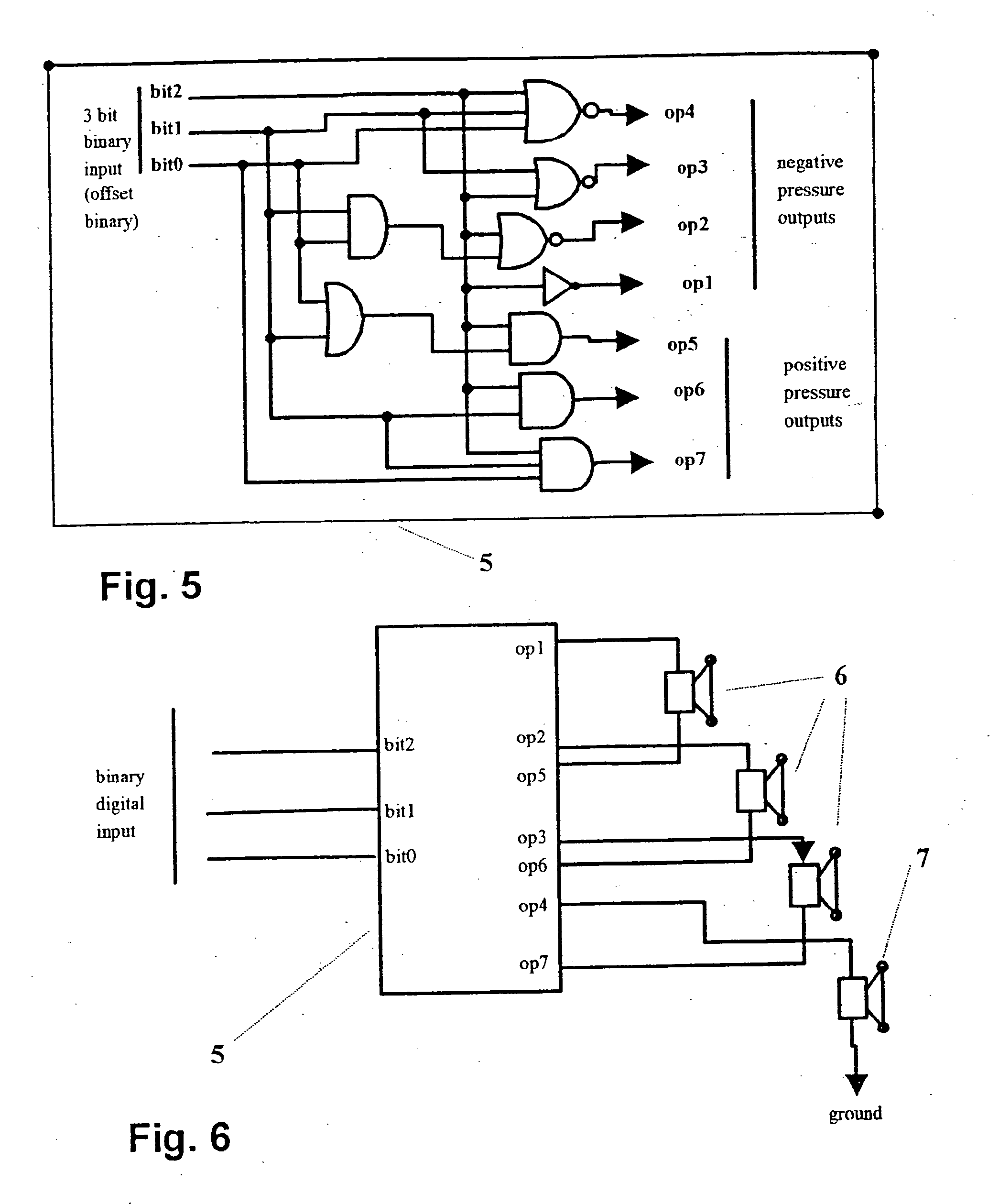
[0097]FIG. 1 illustrates a digital loudspeaker in which the present invention may be applied. A digital input signal of some kind representing a sound pressure waveform is received by the apparatus at the input buffer 1 on n input signal paths. This digital signal may be in any digital code form (e.g. binary code, decimal code, in serial or parallel format). For the purposes of explanation only we assume a binary code input signal of n bits, where one of the bits is a sign bit indicating the polarity of the input signal though the invention is not in any way limited to this input format. The input buffer 1 presents a uniform impedance to the input signal(s) and performs any necessary level conversion and / or serial to parallel conversion before presenting the n parallel binary bits to the encoder 2. The encoder 2 encodes the n bit binary input code into N unary signals, one of which is a unary sign or polarity signal indicating whether the remaining N−1 unary signals represent a posi...


PUM


Abstract

A digital pulse-width-modulation (PWM) generator comprising: an n bit digital magnitude comparator having first and second n bit inputs and an output indicative of the relative values of the signals applied at the first and second inputs; a first n bit digital up / down counter having a count direction input coupled to receive a sign bit of a digital unary input signal, an n bit parallel binary count output connected to the first n bit input of the magnitude comparator, and a clock input; a second n bit counter having a clock input coupled to receive a constant rate clock signal and an n bit parallel binary count output connected to the second n bit input of the magnitude comparator; an AND gate having a first input coupled to receive the constant rate clock signal in frequency divided form and a second input coupled to receive a magnitude portion of the digital unary input signal, and further having an output connected to the clock input of the first counter; and wherein the comparator continually generates an output signal indicative of the relative magnitudes of the counts of the first and second counters, whereby said output signal is a PWM output signal with an average value representing a ramp voltage having a slope determined by magnitude portion of the digital unary input signal with a direction of a slope of the output signal being determined by the polarity of the sign bit.

Description

CROSS REFERENCE TO RELATED APPLICATIONS [0001] This application is a continuation of U.S. patent application Ser. No. 09 / 848,752, filed May 2, 2001, which is a division of U.S. patent application Ser. No. 08 / 930,360, filed Sep. 30, 1997, bit of which are fully incorporated herein by reference.TECHNICAL FIELD [0002] This invention relates to a digital pulse-width-modulation generator which may be used in a loudspeaker for providing sound from electrical signals. BACKGROUND & PRIOR ART [0003] Conventional analogue loudspeakers rely for their operation on the motion of a diaphragm which is driven by some type of electromechanical motor, moving coil being the most common, though electrostatic, piezoelectric and ionisation devices have all been tried and used. The analogue loudspeaker as a whole attempts to reproduce the desired sound by moving all or part of the diaphragm closely in synchronism with a smoothly varying analogue electrical signal which is usually interpreted as representi...

Claims


Application Information

Patent Timeline
Patent Type & Authority Applications(United States)
IPC IPC(8): H03K7/08H03F99/00H03M1/76H04R1/00H04R1/22H04R1/40H04R3/00H04R3/12H04R27/00
CPCH03K7/08H04R1/005H04R1/227H04R2430/20H04R3/12H04R27/00H04R2203/12H04R1/403
Inventor HOOLEY, ANTHONY
Owner YAMAHA CORP
Why Eureka
Try Eureka