Fuel cell system and control method thereof

Inactive Publication Date: 2006-03-09
NISSAN MOTOR CO LTD
View PDF4 Cites 17 Cited by
  • Summary
  • Abstract
  • Description
  • Claims
  • Application Information

AI Technical Summary

Benefits of technology

[0007] The fuel cell system according to the present invention overcomes the above-described problem by causing the control unit to calculate an integration value resulting from integration of a value per unit time concerning a gas to be supplied to the fuel electrode, which varies in accordance with a gas pressure of the oxidant electrode and a temperature of the fuel cell stack, when the open/close valve is set in a closed state, and control the open/close valve in an open state when the integration value becomes equal to or greater than an accumulation threshold value.
[0008] Another fuel cell system according to the present invention overcomes the above-described problem by causing the control unit to calculate an integration value resulting from integration of a discharge gas flow rate from the open/close valve, which varie

Problems solved by technology

However, a reduction in the degree of power generation of the above-described fuel cell system differs depending on the operational load of the fuel cell stack and there may be a case where even if the degree of power generation hardly falls in a low-load area, the degree of power generation has already droppe

Method used


Image

  • Fuel cell system and control method thereof
  • Fuel cell system and control method thereof
  • Fuel cell system and control method thereof

Examples


first embodiment

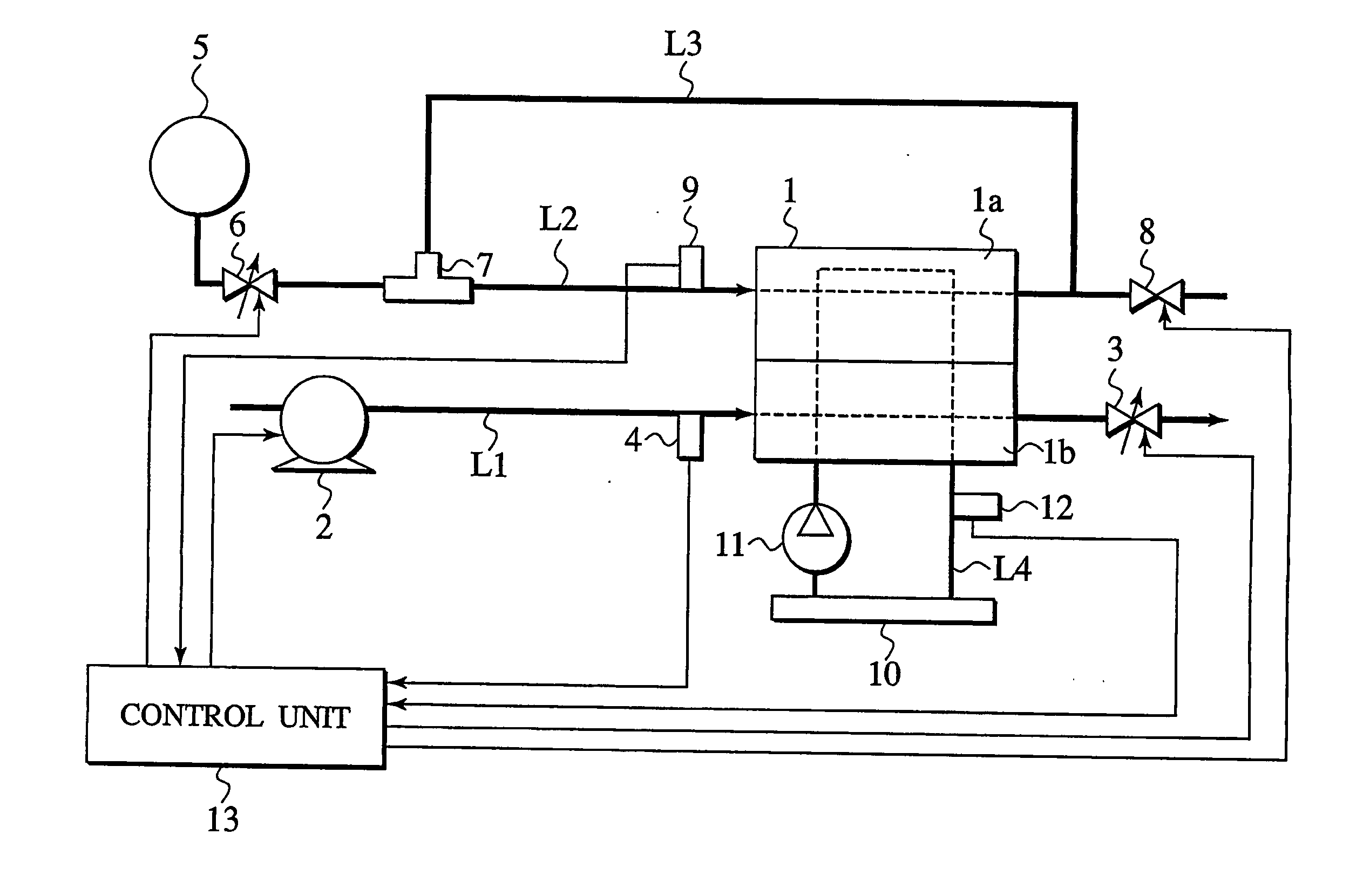
[0022] The present invention is adapted to a fuel cell system according to the first embodiment of the invention configured as shown in FIG. 1.

Configuration of Fuel Cell System

[0023] As shown in FIG. 1, this fuel cell system has a fuel cell stack 1 which generates power as a fuel gas and an oxidant gas are supplied. This fuel cell stack 1 is configured as a fuel cell configuration having an air electrode and a hydrogen electrode provided facing each other with a solid polymer electrolyte membrane in between is held with a separator and a plurality of cell configurations are laminated. In this embodiment, a fuel cell system is described which supplies a hydrogen gas to a hydrogen electrode 1a as a fuel gas for the fuel cell stack 1 to generate a power generation reaction and supplies oxygen to an air electrode 1b as an oxidant gas.

[0024] At the time of causing the fuel cell stack 1 to generate power, this fuel cell system supplies a humidified hydrogen gas to the hydrogen electro...

second embodiment

[0056] A fuel cell system according to the second embodiment is described next. With regard to those portions which are similar to the portions of the above-described first embodiment, same reference symbols are given and their detailed description is omitted. Because the configuration of the fuel cell system according to the second embodiment is the same as that of the first embodiment, its description is omitted too.

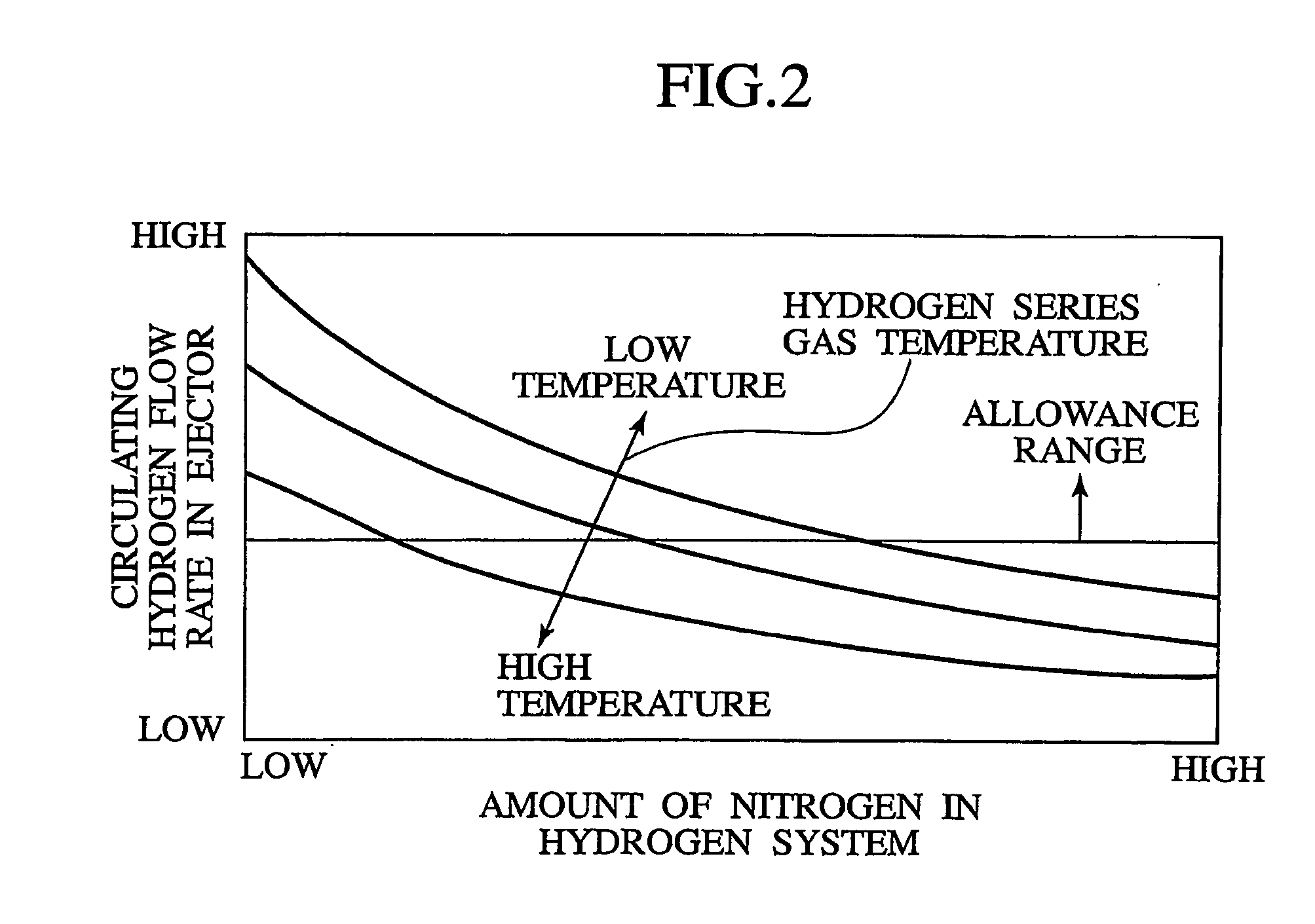
[0057] The fuel cell system according to the second embodiment is d in that the discharge threshold value is changed according to the temperature of the fuel cell stack 1. The fuel cell system according to the second embodiment is also characterized in that in place of the previous flow rate of transmitted nitrogen (integration value) used in the step, the integration initial value is used in the first purge valve control process after the hydrogen purge valve 8 is changed to the closed state from the open state.

[0058] According to the fuel cell system, as shown in F...


PUM


Abstract

A control unit calculates an integration value resulting from integration of the amount of an impurity other than a fuel gas at a hydrogen electrode, which varies in accordance with a gas pressure at the hydrogen electrode and the temperature of a fuel cell stack, when a hydrogen purge valve is set in a closed state and controls the hydrogen purge valve in an open state when the integration value becomes equal to or greater than a threshold value. The control unit calculates an integration value resulting from integration of a discharge gas flow rate from the hydrogen purge valve, which varies in accordance with the gas pressure at the hydrogen electrode and the temperature of the fuel gas, when the hydrogen purge valve is set in the open state and controls the hydrogen purge valve in the closed state when the integration value becomes equal to or greater than a threshold value. This makes it possible to eliminate impurities culminated in a fuel gas system, to ensure stable power generation over a wide range of operational load, and to minimize the amount of fuel discharge, thereby improving the efficiency of fuel usage.

Description

TECHNICAL FIELD [0001] The present invention relates to a fuel cell system and control method thereof suitable at the time of supplying a fuel gas and an oxidant gas to a fuel cell stack to generate power to drive a vehicle driving motor. BACKGROUND ART [0002] A fuel cell system for generating a drive torque for a movable body of a vehicle is known through a technique disclosed in Japanese Patent Laid-Open Publication No. 2000-243417. Such a fuel cell system normally has a solid polymer type fuel cell stack which uses hydrogen as fuel and can ensure stable power generation by supplying more hydrogen than is consumed by the fuel cell stack. [0003] The fuel cell system according to the patent publication supplies more hydrogen than is consumed without discarding excess hydrogen by circulating the excess hydrogen, discharged from the fuel cell stack, to the fuel inlet side of the fuel cell stack. Also, paying attention also to accumulation of an impurity gas other than hydrogen in the ...

Claims


Application Information

Patent Timeline
IPC IPC(8): H01M8/04H01M8/10H01M8/06
CPCH01M8/04007H01M8/04089Y02E60/50H01M8/0662H01M8/04097H01M8/04
Inventor KAMIHARA, TETSUYA
Owner NISSAN MOTOR CO LTD
Why Eureka
Try Eureka