
Roof providing improved passive ventilation and energy efficiency

a technology of roof and roof plate, which is applied in the field of roof plate, can solve the problems of increasing the temperature inside the building, increasing not satisfactorily minimizing the risk of water leakage, so as to improve the energy efficiency and improve the energy efficiency of the building. , the effect of increasing the energy efficiency of the building

Inactive Publication Date: 2006-03-09
DANIELS WILLIAM B II
View PDF24 Cites 39 Cited by
  • Summary
  • Abstract
  • Description
  • Claims
  • Application Information

AI Technical Summary

Benefits of technology

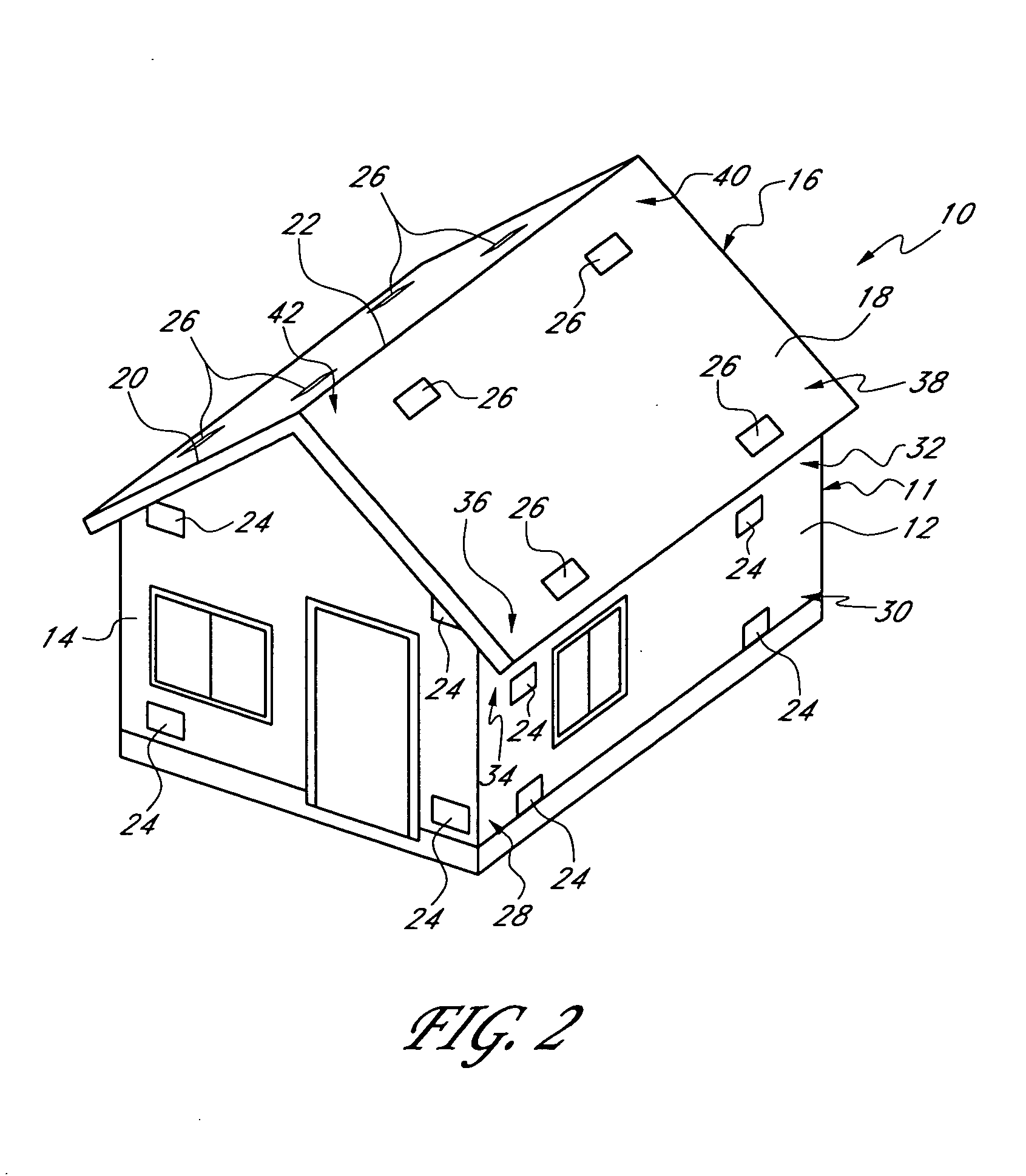
[0012] In various aspects, the present invention includes a roof design that significantly increases the energy efficiency of a building, such as a residential home and / or commercial building. This roof design is particularly useful in passively ventilated buildings, especially in warmer climates. This design improves energy efficiency by reducing the temperature inside the building and, optionally, by absorbing and collecting solar radiation at the roof. The temperature inside the building is reduced by providing a roof design that improves passive ventilation through the roof. The interior temperature is further reduced by providing a roof design that reflects radiation and resists heat conduction through the roof.
[0013] In some embodiments, the roof includes a canopied ridgeline vent that improves passive ventilation. In some embodiments, the roof includes at least one air layer that insulates against conductive heat transfer through the roof. The air layer can be ventilated and / or in fluid communication with the building interior to enhance the heat-insulation property of the air layer. In some embodiments, the roof includes at least one layer of insulation material that reflects solar radiation away from the roof. In some embodiments, the roof is covered with panels for absorbing and collecting solar power at the roof.

Problems solved by technology

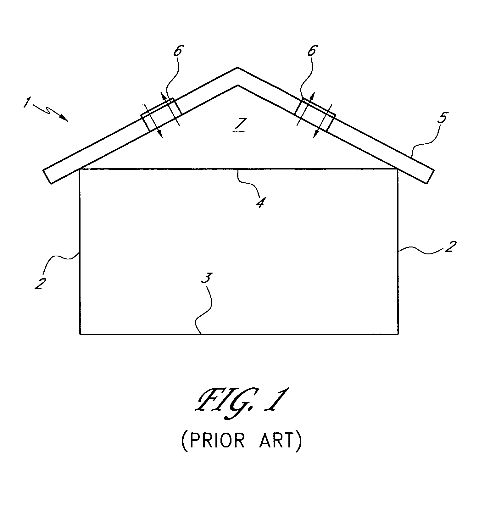
While this permits ventilation of the attic, the remainder of the house is usually not passively ventilated because the attic is closed off from the rest of the house.
However, the risk of water leakage has not been satisfactorily minimized in such designs.
A typical roof absorbs a significant amount of solar radiation, which can cause the attic and even the rest of the building to become very hot.

Method used


Image

  • Roof providing improved passive ventilation and energy efficiency
  • Roof providing improved passive ventilation and energy efficiency
  • Roof providing improved passive ventilation and energy efficiency

Examples


Embodiment Construction

[0056] Conventional systems for passive ventilation of buildings are limited in their ability to adequately ventilate a building. For example, while passive stack ventilation provides some passive ventilation of a building, it has been restricted to kitchens, bathrooms, and / or laundry rooms. While the stack vents may extend through other (non-pollutant) rooms of the building, they do not permit venting of said rooms because the stack vents are not open to such rooms. Also, passive stack ventilation is somewhat restricted because it involves the flow of air through elongated stack vents, which sometimes include turns and irregular configurations. Adequate ventilation through the stack vents is often dependent upon suction at the upper ends of the stack vents, due to a venturi effect caused by winds above the building. The stack vents inhibit the building from “breathing” freely. Thus, buildings having stack vents, perhaps in combination with vents in the floor or exterior walls, prov...


PUM


Abstract

An elongated roof ridgeline vent is disclosed, comprising an elongated opening in a roof-cover along the ridge and a canopy or cover over the opening. Baffles may be provided between the canopy and the roof-cover to prevent wind-driven rain from entering the opening. Screens or other filtering elements can be provided to prevent the ingress of insects, vermin, and debris through the opening. Also disclosed is a roof employing upper and lower roof-covers spaced apart to form an air insulation layer, with a ridgeline vent in the upper roof-cover. The air layer additionally acts as a ventilation path for air from the attic. Also disclosed are eave vents, undereave vents, and layers for reflecting or absorbing solar radiation. Additionally disclosed are embodiments that employ these ventilation principles in a roof-portion with an upper apex, such as a conical roof.

Description

CLAIM FOR PRIORITY [0001] This application claims the priority benefit under 35 U.S.C. § 119(e) of Provisional Application Ser. Nos. 60 / 607,354, filed Sep. 2, 2004; 60 / 619,708, filed Oct. 15, 2004; and 60 / 639,145, filed Dec. 22, 2004. The full disclosures of these priority applications are incorporated herein by reference.BACKGROUND OF THE INVENTION [0002] 1. Field of the Invention [0003] The present invention relates generally to building ventilation and more specifically to a roof system providing passive ventilation, insulation, and, optionally, power generation. [0004] 2. Description of the Related Art [0005] Many buildings are ventilated with so-called “active ventilation” or “mechanical ventilation” apparatus, which typically involves the use of mechanical devices such as fans, air conditioners, etc., which create a forced flow of air through various ducts and vents of the building. In many cases, it is desirable to avoid active ventilation in order to reduce energy requiremen...

Claims


Application Information

Patent Timeline
IPC IPC(8): F24F7/02F24F7/003
CPCE04D12/004E04D13/17F24F2007/004E04D13/178F24F7/02E04D13/174F24F7/003
Inventor DANIELS, WILLIAM B. II
Owner DANIELS WILLIAM B II
Learn More