Power drive unit

a technology of power drive and drive pin, which is applied in the direction of marine propulsion, vessel construction, instruments, etc., can solve the problems of increasing the distance between the control circuit board and current sensors, increasing the overall size of the pdu, and increasing the number of components. , to achieve the effect of minimizing the size and stress produced in the lead pin

Inactive Publication Date: 2006-03-09
KEIHIN CORP +1
View PDF3 Cites 61 Cited by
  • Summary
  • Abstract
  • Description
  • Claims
  • Application Information

AI Technical Summary

Benefits of technology

[0011] An object of the present invention is therefore to overcome the foregoing drawbacks by providing a power drive unit in which the control circuit board and current sensors can be connected through lead pins wit

Problems solved by technology

However, the PDU of this prior art with a harness disadvantageously increases both the number of components and the number of assembly steps.
However, when the configuration taught by the second reference ('955) is applied to the PDU, the distance

Method used


Image

  • Power drive unit
  • Power drive unit
  • Power drive unit

Examples


first embodiment

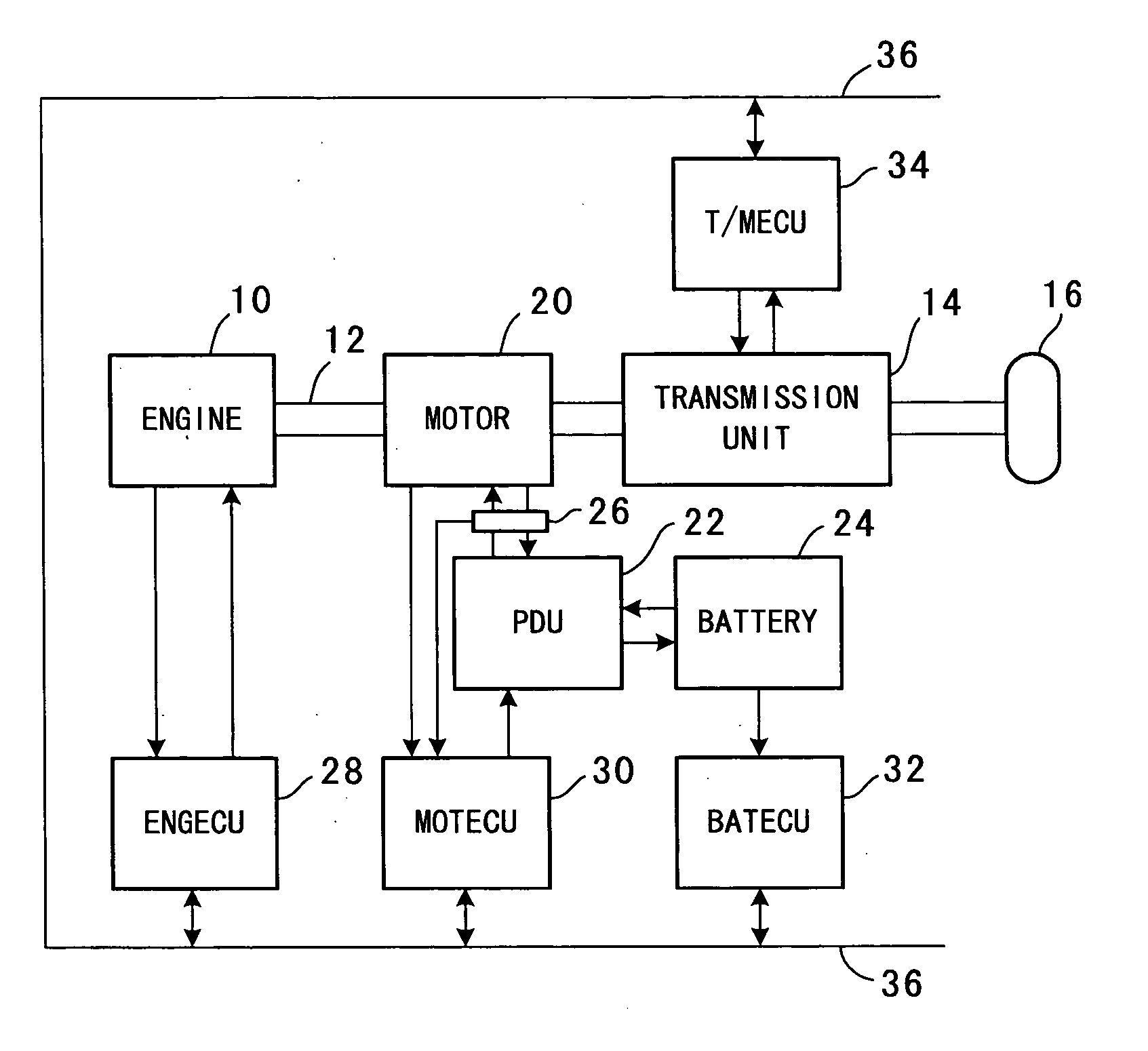
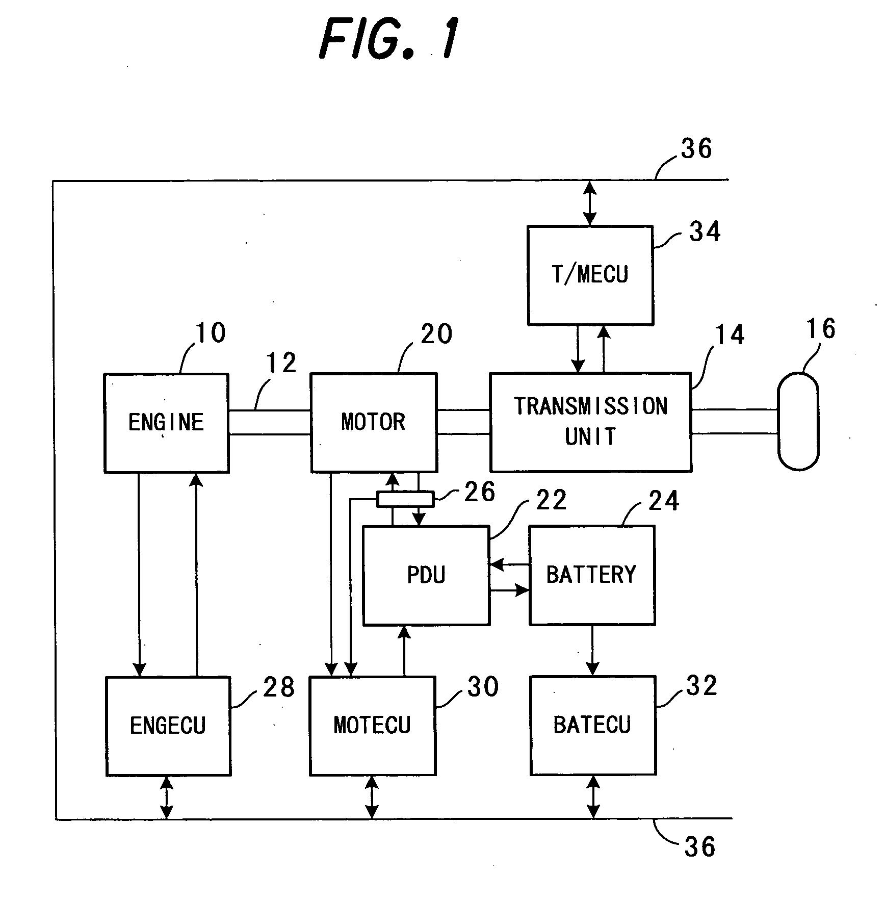
[0030]FIG. 1 is a block diagram showing the overall configuration of a hybrid vehicle control system including a power drive unit according to the present invention.

[0031] Reference numeral 10 in the drawing designates an internal combustion engine. The output of the engine 10 is inputted through a drive shaft 12 to a transmission unit 14. The engine 10 is a gasoline-injection, spark-ignition, four-cylinder engine. The transmission unit 14 is an automatic transmission and connected to driven wheels 16 (only one shown) of the hybrid vehicle (not shown) on which the engine 10 is mounted. The transmission unit 14 changes the speed of the engine rotation and transmits it to the driven wheels 16 for running the hybrid vehicle.

[0032] The drive shaft 12 is connected with or passes through an electric motor 20 between the engine 10 and the transmission unit 14. The engine 10 is started by supplying cranking current to the motor 20 and cranked by the motor, whereafter the motor 20 rotates s...

second embodiment

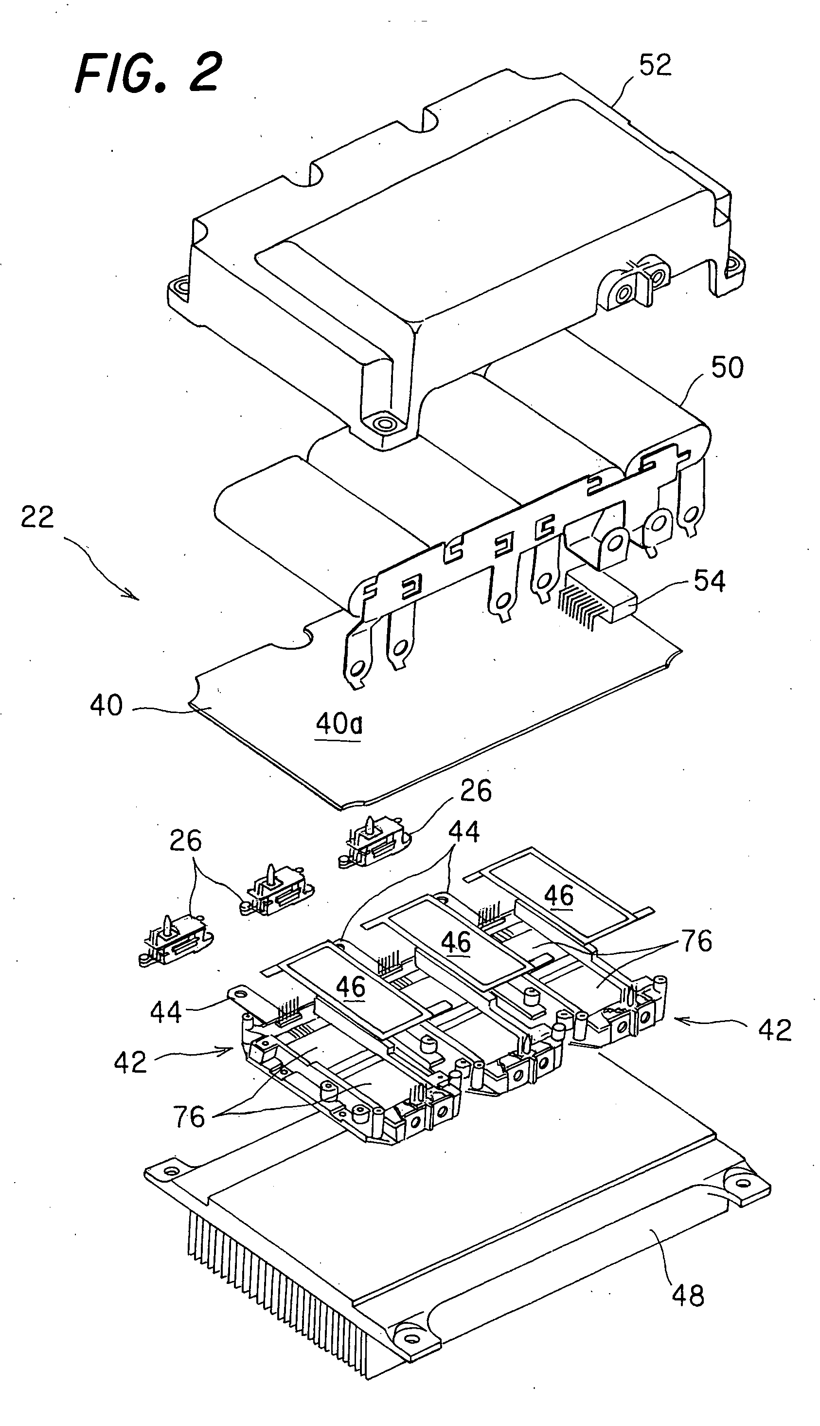
[0081] A power drive unit according to the invention will now be explained with particular focus on the current sensors of the power drive unit.

[0082]FIG. 14 is a partial enlarged plan view showing a power drive unit according to a second embodiment of the present invention and illustrating the current sensor 26 fastened to the heat sink 48 and FIG. 15 is an enlarged side view of the portion shown in FIG. 14. The power modules 42 and other components are omitted from the drawing in the interest of simplicity.

[0083] As pointed out above, the bus bars 44 extending from the power modules 42 pass alternating current supplied to the motor 20. This alternating current is often of a relatively high voltage.

[0084] In the first embodiment, the bus bars 44 project in parallel with the upper surface 48a of the heat sink 48 (horizontally as viewed in the drawings), so that the gaps or distances between the bus bars 44 and the upper surface 48a of the heat sink 48 are relatively narrow.

[0085]...


PUM


Abstract

In a power drive unit having power modules (three-phase inverter circuits) connected to a control circuit board, bus bars extending from the power modules and a current sensor each installed near the bus bars and including a sensing element that detects currents outputted from the bus bars, there are provided a sensor board on which the sensing element is mounted, and lead pins each connecting the sensor board to the control circuit board and having a bowed shape whose one end is connected to the sensor board and other end once extends away from the circuit board and then turns back toward the circuit board. With this, the circuit board and current sensors can be connected through the lead pins without increasing the distance therebetween and stress produced in the lead pins can be alleviated, thereby enabling the unit to be minimized in size and utilized in a harsh service environment.

Description

BACKGROUND OF THE INVENTION [0001] 1. Field of the Invention [0002] This invention relates to a power drive unit, more specifically to a power drive unit that is most suitable for use in a hybrid vehicle. [0003] 2. Description of the Related Art [0004] The hybrid vehicle that has emerged in various forms in recent years is equipped with an internal combustion engine, electric motor(s), battery or other such energy storage device, and the like. During driving of the hybrid vehicle, the engine and motor(s) are controlled in response to the driving or running conditions of the vehicle (e.g., whether the vehicle drives at high speed or low speed). [0005] The electric motor used in a hybrid vehicle is generally operated by alternating current supplied to its stator from a power drive unit (PDU), more exactly from power modules in the PDU that convert direct current (outputted from a battery or other energy storage device) into alternating current. [0006] In the PDU, alternating currents ...

Claims


Application Information

Patent Timeline
IPC IPC(8): B63H21/17H02M7/48
CPCH05K7/1432H05K7/14329
Inventor KUBOKAWA, MINORUNAKAMURA, TAKESHIIIJIMA, TAKAAKI
Owner KEIHIN CORP
Why Eureka
Try Eureka