
Common protocol layer architecture and methods for transmitting data between different network protocols and a common protocol packet

a network protocol and protocol layer technology, applied in the direction of digital computers, wireless network protocols, instruments, etc., can solve the problems of cpu time delay generation, large loss in performance, and communication between more than two systems with different protocols

Active Publication Date: 2006-03-09
KOREA ELECTRONICS TECH INST
View PDF20 Cites 34 Cited by
  • Summary
  • Abstract
  • Description
  • Claims
  • Application Information

AI Technical Summary

Benefits of technology

The present invention provides a common protocol layer architecture and methods for transmitting data between different network protocols using a common protocol packet. The common protocol layer architecture enables data communications between different network protocols and provides an internal interface for QoS, security, and communication management inside a home station chip. The common protocol packet comprises a common protocol header with information about a packet and a payload with the contents of data. The invention provides a solution for the increasing number of network protocols and middlewares in home networking and allows for the acceptance of various protocols and conversion techniques on the protocol layers for communications between them.

Problems solved by technology

However, communications between more than two systems with different protocols is restricted.
In those conventional protocol converters, time delay is generated while the CPU performs other tasks.
In addition, while one CPU receives signals and exchanges responses with the inside of system, a load on the CPUs and a waste of time are caused thereby incurring a large loss in the view of performance.
Therefore, for data exchange between various network protocols having various protocol layers, a lot of conversion methods are required thereby causing great complexity.
Although it shows less complexity in converting network protocols compared to the first method, it still requires a lot of protocol conversions.
They do not perform particular conversions and are not data exchange methods between different network protocols.
However, the above-mentioned conventional protocol conversion methods have problems such as complexity in conversion methods, complexity due to different layer architectures and roles of protocols, and complexity in accessing apparatuses in different networks.
In other words, the number of conversion methods increases in proportion to the number of network protocols to be converted and the number of layers in the network protocols to be converted, thereby increasing complexity.
In addition, when the protocol conversion is performed, the complexity increases by times of a particular factor, because the protocol layer architectures and roles of each layer in each network protocol are very different based on the seven-layered OSI model.
Moreover, there is no common address hierarchy recognizable between different network apparatuses when communications between the different network apparatuses are performed.

Method used


Image

  • Common protocol layer architecture and methods for transmitting data between different network protocols and a common protocol packet
  • Common protocol layer architecture and methods for transmitting data between different network protocols and a common protocol packet
  • Common protocol layer architecture and methods for transmitting data between different network protocols and a common protocol packet

Examples


Embodiment Construction

[0058] Reference will now be made in detail to the preferred embodiments of the present invention, examples of which are illustrated in the accompanying drawings.

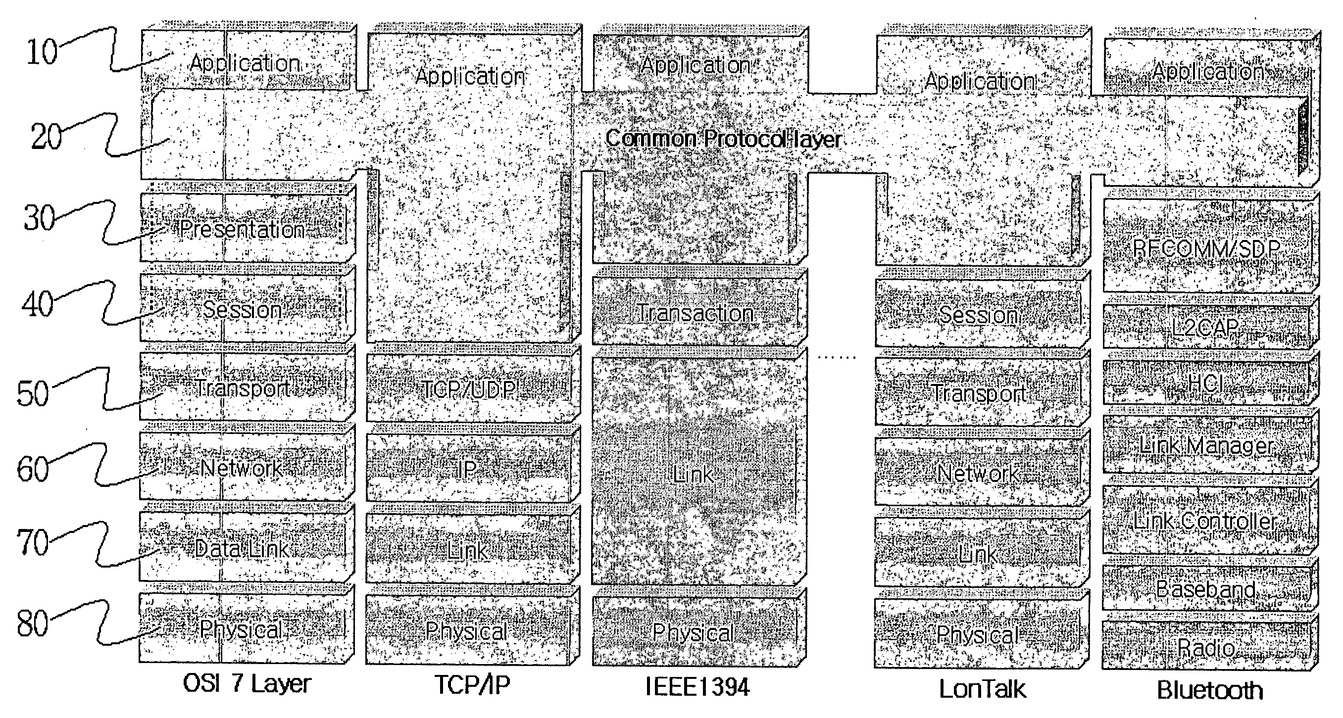
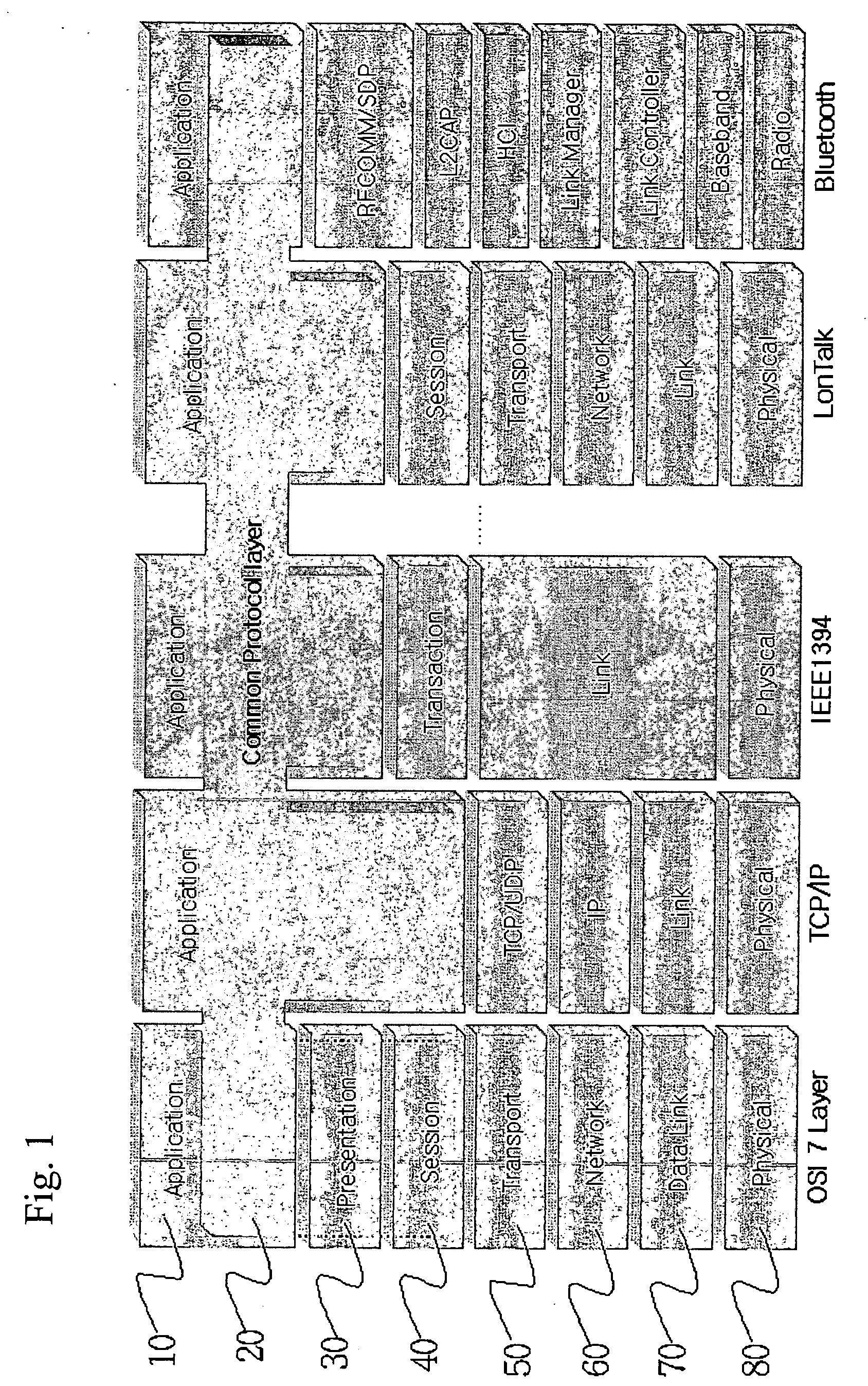
[0059]FIG. 1 is a structure chart of common protocol layer architecture according to the present invention. In FIG. 1, a common protocol layer may be positioned within or under an existing application layer (10). A network protocol comprising the common protocol layer includes all network protocols based on the OSI reference model. For example, there are TCP / IP used in networks such as Internet, Intranet or Extranet, IEEE 1394 protocol used in network communications under Linux operating systems, LonTalk protocol that embodies user-oriented systems, and Bluetooth protocol used in wireless networks.

[0060] A method of transmitting data through network protocol layers according to the present invention comprises the steps of: [0061] transmitting data through an application layer which enables communications services between ...


PUM


Abstract

The present invention provides common protocol architecture and methods for transmitting data between different network protocols and a common protocol packet. The common protocol architecture comprises an application layer; a common protocol layer positioned under the application layer, the common protocol layer enabling data communications between the different protocols; a presentation layer positioned under the common protocol layer; a session layer positioned under the presentation layer; a transport layer positioned under the session layer; a network layer positioned under the transport layer; a data link layer positioned under the network layer; and a physical layer positioned under the data link layer. The common protocol packet comprises a common protocol header with information about a packet and a payload with the contents of data. By designing the common protocol layer and the common protocol packet accepting various. protocols simultaneously, the present invention can improve compatibility between different protocols.

Description

TECHNICAL FIELD [0001] The present invention relates to a common protocol architecture for transmitting data between different network protocols and, more particularly, an architecture of a common protocol layer and a structure of a common protocol packet, which adopt various network protocols such as IP, Bluetooth, IEEE1394, and LonTalk and enable communication among them. BACKGROUND ART [0002] In the modem telecommunications industry, standard communications systems are linked to each other using protocols based on the Open Systems Interconnection (hereinafter referred to as “OSI”) model. The goal of OSI is to create an open system networking environment where any vendor's computer system, connected to any network, can freely share data with any other computer system on that network. In fact, the OSI model would allow any terminal connected to any computer to access any application on any other computer provided that the computers were connected by some form of common network. In ...

Claims


Application Information

Patent Timeline
Patent Type & Authority Applications(United States)
IPC IPC(8): G06F15/16H04L29/06
CPCH04L69/08H04L69/085H04W80/00
Inventor CHOI, KWANG-SOONLIM, SEUNG-OKJUNG, KWANGMOSEO, KYEUNG-HAK
Owner KOREA ELECTRONICS TECH INST
Learn More