
Tank for very low temperature liquids

a tank and liquid technology, applied in the direction of container discharging methods, vessel construction details, transportation and packaging, etc., can solve the problems of fuel leakage through cracks, high manufacturing cost, heavy weight, etc., and achieve the effect of preventing crack generation

Active Publication Date: 2006-03-16
SUBARU CORP
View PDF2 Cites 24 Cited by
  • Summary
  • Abstract
  • Description
  • Claims
  • Application Information

AI Technical Summary

Benefits of technology

[0016] Therefore, according to the present invention, since the inner shell is comprised of the fiber-reinforced resin composite that can withstand temperatures above the melting point of the airtight resin layer, it is possible to form the airtight resin layer by “heat-bonding” a thermoplastic airtight resin (such as a liquid crystal polymer) onto the inner surface of the inner shell. Moreover, since there is no adhesive layer between the pressure-resistant layer (the inner shell) and the airtight resin layer, generation of cracks is prevente

Problems solved by technology

A conventional airtight tank is made of a metal; thus, its weight is heavy and manufacturing cost is high.
However, a composite material comprised of an epoxy resin reinforced with a fiber, upon contact with a cryogenic liquid, has many micro cracks in the epoxy resin due to the difference in thermal expansion between the epoxy and the reinforcing fiber, thereby causing a fuel leak through the cracks.
The repetition of filling up a tank with a cryogenic liquid and discharging it means a frequent change in temperature between cryogenic and normal, thereby causing frequent contraction and expansion of the composite material comprising the tank.
Thus, for the case of the tank with the liquid crystal polymer layer and the adhesive, cracks are generated in the adhesive layer connecting the liquid crystal polymer film pieces because of the difference in thermal expansion between the composite material and the adhesive.
This poses a new problem, i.e. a fuel leak through the cracks in the adhesive layer.
This problem occurs similarly even when the improved composite material, as disclosed in Japanese Kokai Laid-open Publication No. 2002-212320, is employed for fabricating the tank.

Method used


Image

  • Tank for very low temperature liquids
  • Tank for very low temperature liquids
  • Tank for very low temperature liquids

Examples


Embodiment Construction

[0030] Embodiments of the present invention are described below in accordance with accompanying drawings.

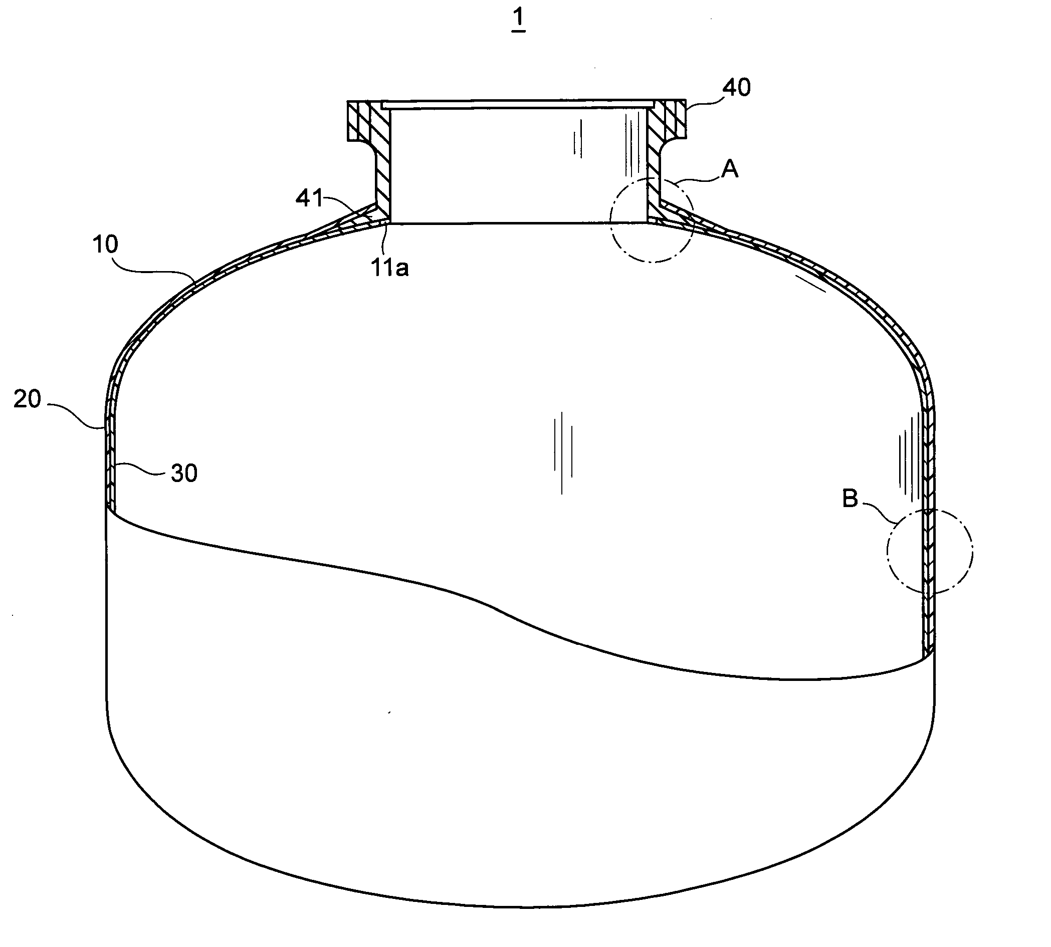
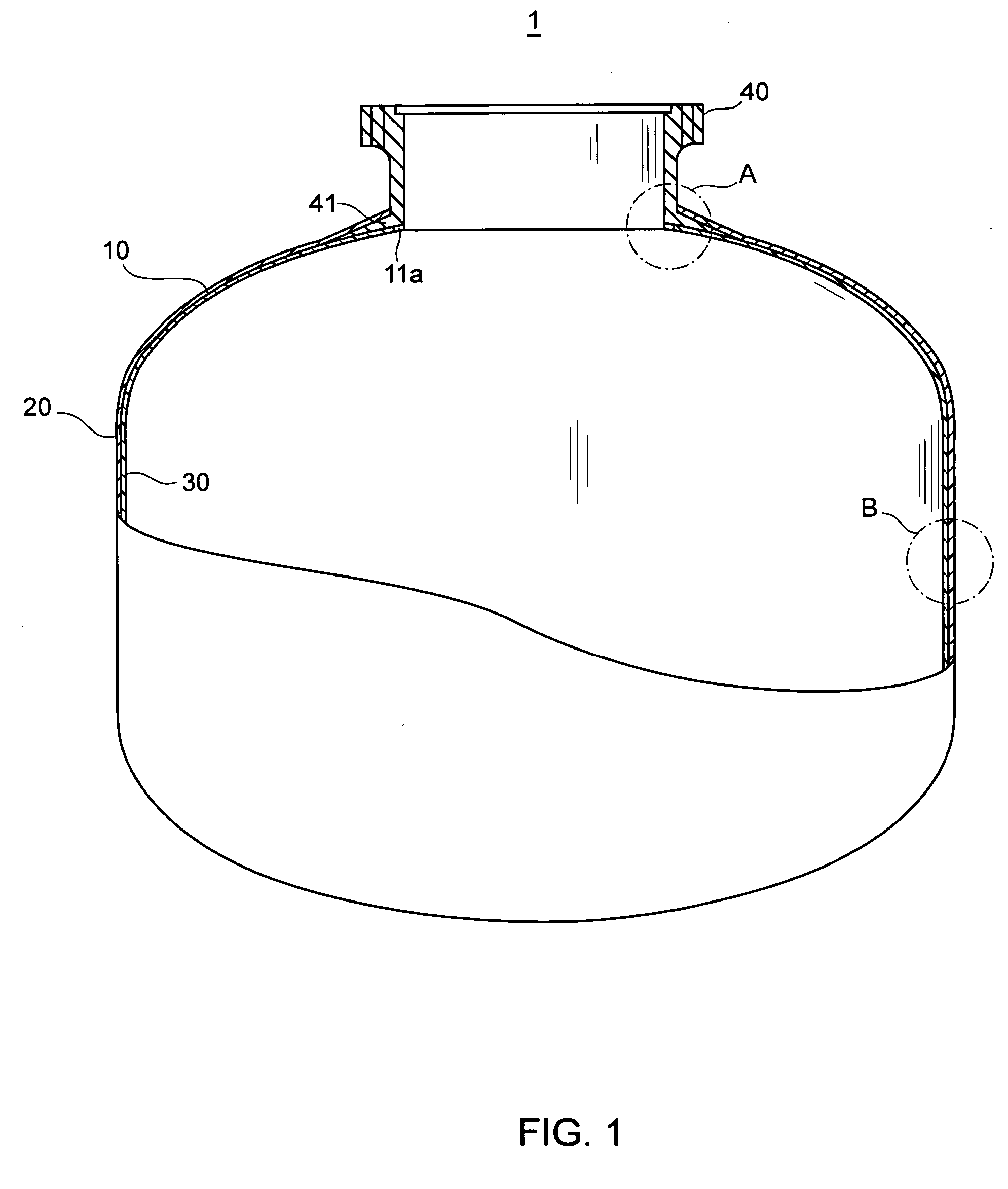
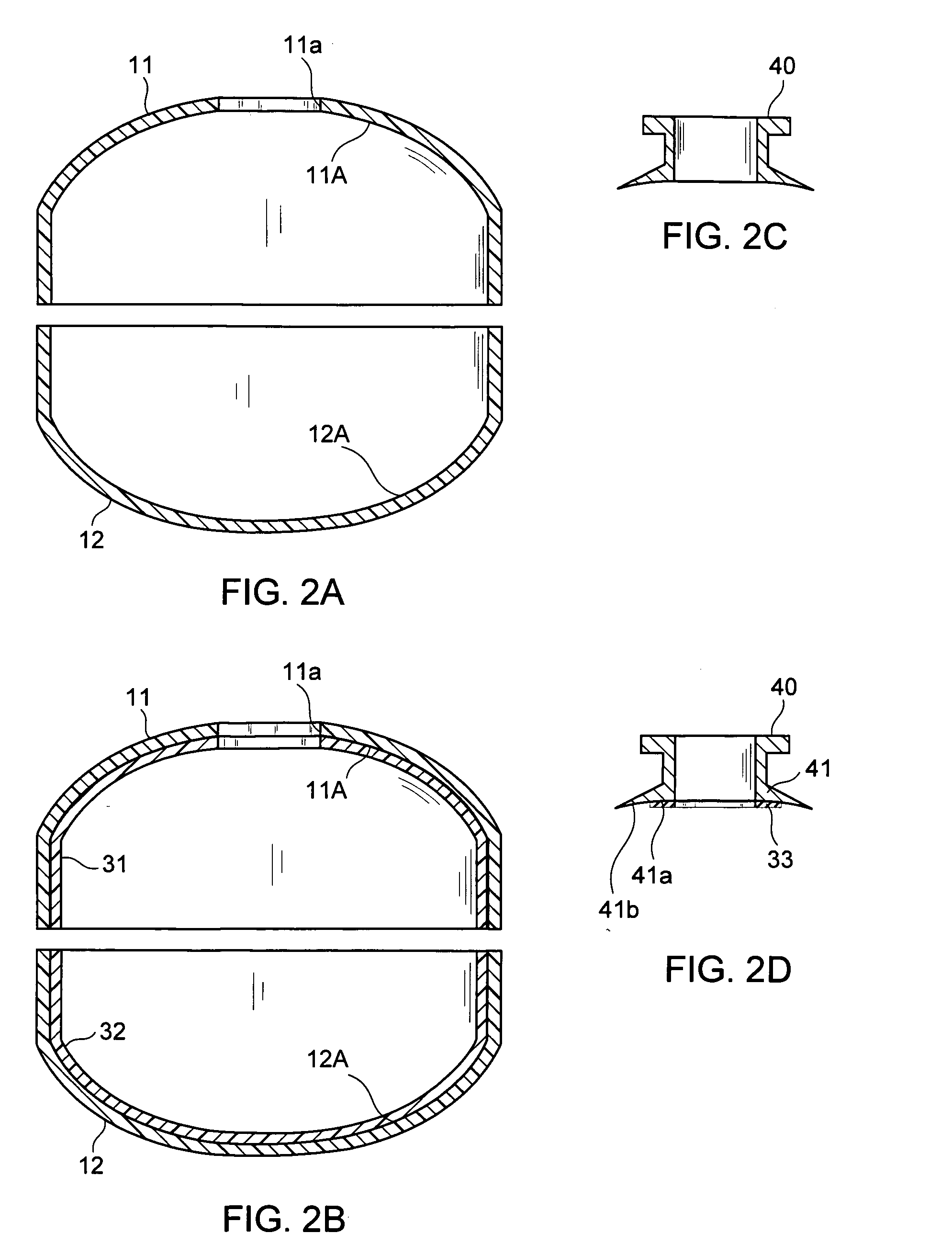
[0031] First, the structure of a tank for cryogenic liquids according to the present invention is explained with reference to the drawings. The tank 1 in FIG. 1 is for holding a cryogenic liquid such as liquid hydrogen, liquid oxygen and the like to be used as fuel for a rocket, and comprises an inner shell 10, an outer shell 20 which is provided on the outer surface of the inner shell 10, and an airtight resin layer 30 which is provided on the inner surface of the inner shell 10, and a joint section40 which is provided in the top section of the tank.

[0032] The inner shell 10 serves for maintaining the shape of the tank, and is comprised of a fiber-reinforced resin composite material which can withstand temperatures above the melting point of the airtight resin layer 30. (That is, neither deformation nor degradation in strength occurs at the melting point of the airtight resin ...


PUM

PropertyMeasurementUnit
Temperatureaaaaaaaaaa
Pressureaaaaaaaaaa
Melting pointaaaaaaaaaa

Abstract

The present invention relates to a tank for holding a cryogenic liquid. According to the present invention, there is provided a light and durable tank which is airtight even at cryogenic temperatures without generating cracks. The tank includes: a pressure-resistant layer having an inner shell and an outer shell; and an airtight resin layer on an inner surface of the inner shell, wherein the inner shell is comprised of a fiber-reinforced resin composite which can withstand temperatures above the melting point of the airtight resin layer, and the outer shell is comprised of another fiber-reinforced resin composite which can be cured at a temperature below the melting point of the airtight resin layer.

Description

CROSS REFERENCE TO RELATED APPLICATIONS [0001] This application claims priority under 35 U.S.C. 119 based upon Japanese Patent Application Serial No. 2004-250829, filed on Aug. 30, 2004. The entire disclosure of the aforesaid application is incorporated herein by reference. FIELD OF THE INVENTION [0002] The present invention relates to a tank for holding a cryogenic liquid such as liquid hydrogen, liquid oxygen and the like. BACKGROUND OF THE INVENTION [0003] A cryogenic liquid, such as liquid hydrogen, liquid oxygen and the like, is used as fuel for a rocket engine. Thus, a fuel tank that can withstand cryogenic temperatures plays an important role in aerospace applications. A conventional airtight tank is made of a metal; thus, its weight is heavy and manufacturing cost is high. For this reason, a composite material which is more durable and lighter than a metal has been a prime candidate for the new generation fuel tank material. However, a composite material comprised of an epox...

Claims


Application Information

Patent Timeline
IPC IPC(8): F17C1/00
CPCF17C1/06Y10T156/1002F17C2201/056F17C2203/0619F17C2203/0646F17C2203/0673F17C2203/0692F17C2203/0697F17C2205/0305F17C2209/22F17C2209/227F17C2209/232F17C2221/011F17C2221/012F17C2223/0161F17C2223/033F17C2260/012F17C2260/036F17C2270/0197Y02E60/321F17C2201/0109Y02E60/32
Inventor MATSUOKA, SEIICHIARAKAWA, YOJI
Owner SUBARU CORP
Learn More