Sintered ring magnet

a sintered ring magnet and ring magnet technology, which is applied in the direction of magnetic circuit rotating parts, magnetic circuit shapes/forms/construction, magnetic bodies, etc., can solve the problems of inability to manufacture compact high-power motors, inability to sufficiently reduce cogging torque, and weak magnetic force produced by bonded magnets, so as to reduce the distortion of magnetization distribution

Inactive Publication Date: 2006-03-16
MITSUBISHI ELECTRIC CORP
View PDF6 Cites 62 Cited by
  • Summary
  • Abstract
  • Description
  • Claims
  • Application Information

AI Technical Summary

Benefits of technology

[0012] The invention is intended to provide a solution to the aforementioned problems of the prior art. Specifically, it is an object of the invention to provide a sintered ring magnet capable of producing a powerful magnetic force, in which corrugations (protrusions and hollows) are formed on a generally cylindrical outer surface of the ring magnet, the corrugations being skewed with respect to an axial direction of the ring magnet, to reduce distortion of magnetization distribution along a circumferential direction of the ring magnet as well as cogging torque.
[0013] It is another object of the invention to provide a sintered ring magnet capable of reducing cogging torque even if magnet shape accuracy is not so high after a sintering process in manufacturing the ring magnet.
[0014] It is still another object of the invention to provide a sintered ring magnet for use in a motor, in which variations in magnetic properties, permeance of a magnetic circuit formed in the motor and saturation status of a motor stator are compensated by the shape of the ring magnet varied along an axial direction thereof to reduce torque fluctuations, such as cogging torque and torque ripple, caused by the aforementioned variations.
[0018] The sintered ring magnet thus structured can produce a well-controlled magnetomotive force distribution with high accuracy and with reduced variations in the amount of magnetic flux in the axial direction of the sintered ring magnet, for example. When installed in a motor, the sintered ring magnet can reduce torque fluctuations, such as cogging torque. Therefore, the sintered ring magnet of the invention serves to increase the amount of effectively working magnetic flux and torque generated by the motor, decrease the amount of exciting current and improve motor efficiency as a result of a reduction in copper loss. Consequently, the sintered ring magnet of the invention can be used for producing a high-power motor.

Problems solved by technology

However, a radially oriented ring magnet has a rectangular magnetization distribution pattern containing a great deal of distortion due to higher harmonic components and, therefore, it is difficult in many cases to sufficiently reduce the cogging torque by skewed magnetization alone.
Generally, magnetic force produced by the bonded magnets is so weak that the bonded magnets can not be used for manufacturing compact high-power motors.
Since the magnetic force produced by the bonded magnets is so weak that the bonded magnets are not applicable to manufacturing servomotors which require a strong magnetic force.
This extrusion molding process has a problem that the magnetic force of the resin-molded magnet which is weak by nature becomes still weaker because it is impossible to increase the magnetic force by applying a magnetic field during the molding process for anisotropically magnetizing the magnet.
Additionally, resin-molded magnets manufactured by the extruder are limited to shapes in which magnetic poles are obliquely formed, or skewed, with respect to an axial direction of the magnet.
In a ring magnet used in a motor, however, magnetic properties of the magnet are not necessarily uniform along the axial direction, the ability of a magnetic circuit to conduct magnetic flux from the ring magnet to a stator, or permeance, varies along the axial direction, and saturation status of the stator varies along the axial direction.
Generally, this manufacturing method is associated with a problem of poor magnet shape accuracy.

Method used


Image

  • Sintered ring magnet
  • Sintered ring magnet
  • Sintered ring magnet

Examples


first embodiment

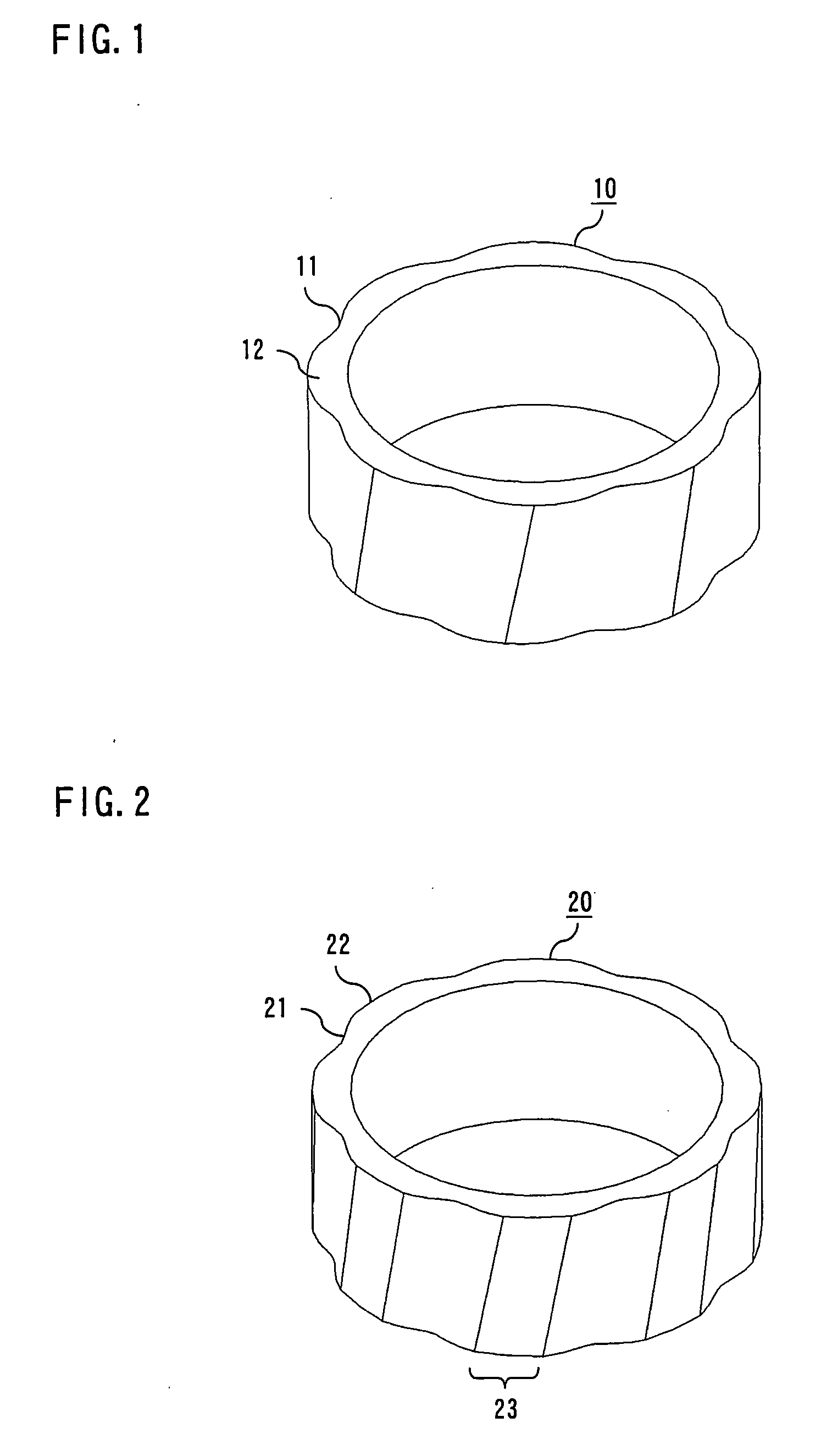
[0060]FIG. 1 is a perspective view of a sintered ring magnet 10 having a ring shape according to a first embodiment of the invention. The sintered ring magnet 10 is a magnet containing neodymium (Nd), iron (Fe) and boron (B) as main components. A generally cylindrical outer surface of the sintered ring magnet 10 is corrugated with alternating hollows 11 and protrusions 12 formed along the sintered ring magnet 10. The hollows 11 and the protrusions 12 are formed at regular intervals around the generally cylindrical outer surface of the sintered ring magnet 10. In the example shown in FIG. 1, the sintered ring magnet 10 has eight each hollows 11 and protrusions 12 alternately formed at specific angular intervals (45°).

[0061] The hollows 11 and the protrusions 12 are formed in parallel lines skewed by a specific inclination angle (skew angle) with respect to an axial direction of the sintered ring magnet 10. Magnetic poles of the sintered ring magnet 10 are formed by skewed magnetizat...

second embodiment

[0069] A sintered ring magnet according to a second embodiment of the invention is also a ring-shaped sintered magnet containing neodymium, iron and boron as main components and having corrugations (protrusions and hollows) formed on a generally cylindrical outer surface like the sintered ring magnet 10 of the first embodiment. The protrusions and the hollows are formed in parallel lines skewed by a specific inclination angle (skew angle) about a longitudinal axis of the ring magnet. Magnetic poles of the ring magnet are formed along the corrugations with boundaries between the adjacent magnetic poles located in the individual hollows. What is characteristic of the sintered ring magnet of this embodiment is that each of the protrusions formed on the generally cylindrical outer surface of the ring magnet constitutes part of an imaginary cylindrical shape which defines an outermost surface of the ring magnet. Thus, as viewed along the longitudinal axis (central axis) of the ring magne...

third embodiment

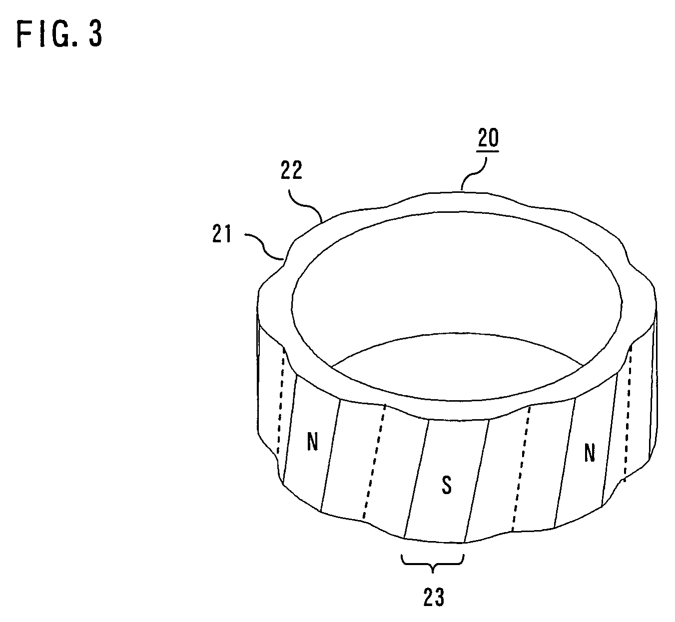
[0073]FIG. 2 is a perspective view of a sintered ring magnet 20 according to a third embodiment of the invention. The sintered ring magnet 20 of this embodiment is a sintered magnet containing neodymium, iron and boron as main components like the sintered ring magnet 10 of the first embodiment. A generally cylindrical outer surface of the sintered ring magnet 20 is corrugated with alternating hollows 21 and protrusions 22 formed along the sintered ring magnet 20. The hollows 21 and the protrusions 22 are formed in parallel lines skewed by a specific inclination angle (skew angle) with respect to an axial direction of the sintered ring magnet 20.

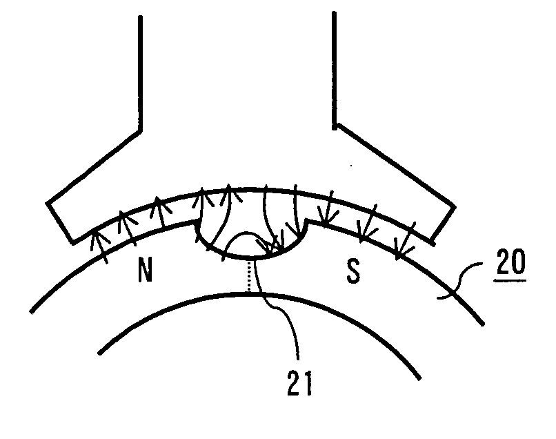
[0074] As shown in FIG. 3, magnetic poles of the sintered ring magnet 20 are formed such that the magnetic poles are aligned parallel to the hollows 21 and the protrusions 22 at the same skew angle with respect to the axial direction of the sintered ring magnet 20. Boundaries of these magnetic poles (shown by broken lines in FIG. 2) are loca...


PUM

PropertyMeasurementUnit
particle sizeaaaaaaaaaa
temperaturesaaaaaaaaaa

Abstract

A sintered ring magnet (10) is produced through processes of magnetically orienting magnetic powder by applying a magnetic field, pressing the magnetic powder and sintering a ring-shaped powder compact (30) thus formed. The sintered ring magnet (10) has a generally cylindrical outer surface with surface corrugations formed by alternating hollows (11) and protrusions (12) at regular intervals around the sintered ring magnet (10) at least in part along an axial direction thereof, wherein the sintered ring magnet (10) varies in cross-sectional shape from one position to next along the axial direction, and magnetic poles are formed along the surface corrugations with boundaries of the magnetic poles located in the hollows (11). The hollows (11) and the protrusions (12) are skewed about a longitudinal axis of the sintered ring magnet (10). The surface corrugations are shaped into a wavy pattern expressed approximately by absolute values of a sine wave.

Description

BACKGROUND OF THE INVENTION [0001] 1. Field of the Invention [0002] The present invention relates to the structure of a sintered ring magnet which is manufactured through a process of pressing magnetic powder in a magnetic field for producing a ring-shaped powder compact and a subsequent process of sintering the ring-shaped powder compact. [0003] 2. Description of the Background Art [0004] Radially oriented ring magnets used in inner rotors of permanent magnet motors are often magnetized with a skew to form magnetic poles aligned at an oblique angle to an axial direction of the ring magnet for reducing fluctuations in rotating speed of the rotor due to cogging torque, for instance. However, a radially oriented ring magnet has a rectangular magnetization distribution pattern containing a great deal of distortion due to higher harmonic components and, therefore, it is difficult in many cases to sufficiently reduce the cogging torque by skewed magnetization alone. [0005] A conventional...

Claims


Application Information

Patent Timeline
Patent Type & Authority Applications(United States)
IPC IPC(8): H02K1/04H02K21/12H02K1/27
CPCB22F7/062H01F1/086H02K15/03H02K1/2733H01F41/028
Inventor IWAMI, TAIZOUGAI, YOSHIKAZUNAKAHARA, YUJI
Owner MITSUBISHI ELECTRIC CORP
Why Eureka
Try Eureka