Method of synthesizing small-diameter carbon nanotubes with electron field emission properties

a carbon nanotube and electron field technology, applied in the manufacture of electric discharge tubes/lamps, electrode systems, discharge tubes luminescnet screens, etc., can solve the problems of catastrophic failure, high cost, and small quantity of materials produced by laser ablation methods, etc., to facilitate catalyst preparation, high quality, and the effect of high emission current density

Active Publication Date: 2006-03-16
NURAY TECH +1
View PDF18 Cites 21 Cited by
  • Summary
  • Abstract
  • Description
  • Claims
  • Application Information

AI Technical Summary

Benefits of technology

[0013] The method of fabrication includes a scalable one-step method for catalyst preparation and a process for the growth of nanotubes using chemical vapor deposition methods. One advantage of the method is the ease of catalyst preparation and the compatibility of the method with industrial scale production. The combination of the catalysts and growth conditions disclosed herein produce high quality small diameter and few-walled carbon nanotubes. The threshold voltage for field emission of electrons from these materials is lower or similar to the results reported for SWNT bundles. Further, these materials display higher emission current density and better long-term stability than prior SWNT bundles.

Problems solved by technology

However at present, macroscopic quantities of materials with discreet individual SWNTs are difficult to obtain.
The laser ablation method, however, is costly and produces a small quantity of materials.
SWNTs can also be damaged by ion sputtering during emission leading to catastrophic failures.

Method used


Image

  • Method of synthesizing small-diameter carbon nanotubes with electron field emission properties
  • Method of synthesizing small-diameter carbon nanotubes with electron field emission properties
  • Method of synthesizing small-diameter carbon nanotubes with electron field emission properties

Examples


Embodiment Construction

[0030] In general, the growth process for nanotubes synthesis involves a series of steps: (1) heating a catalyst material to high temperature, usually between 700° C. to 1000° C. The catalysts usually are nanoparticles composed of transition metals supported on either porous or flat supports. The catalyst can also be metal nanoparticles formed in gas phase and floating in the flow of feeding gas; (2) introduction of precursor gas containing a carbon source into the furnace; (3) diffusion and decomposition of precursor on the surface of catalyst nanoparticles and dissolution of carbon atoms within the metal nanoparticles; and (4) nucleation and growth of nanotubes from the metal nanoparticles saturated with carbon atoms.

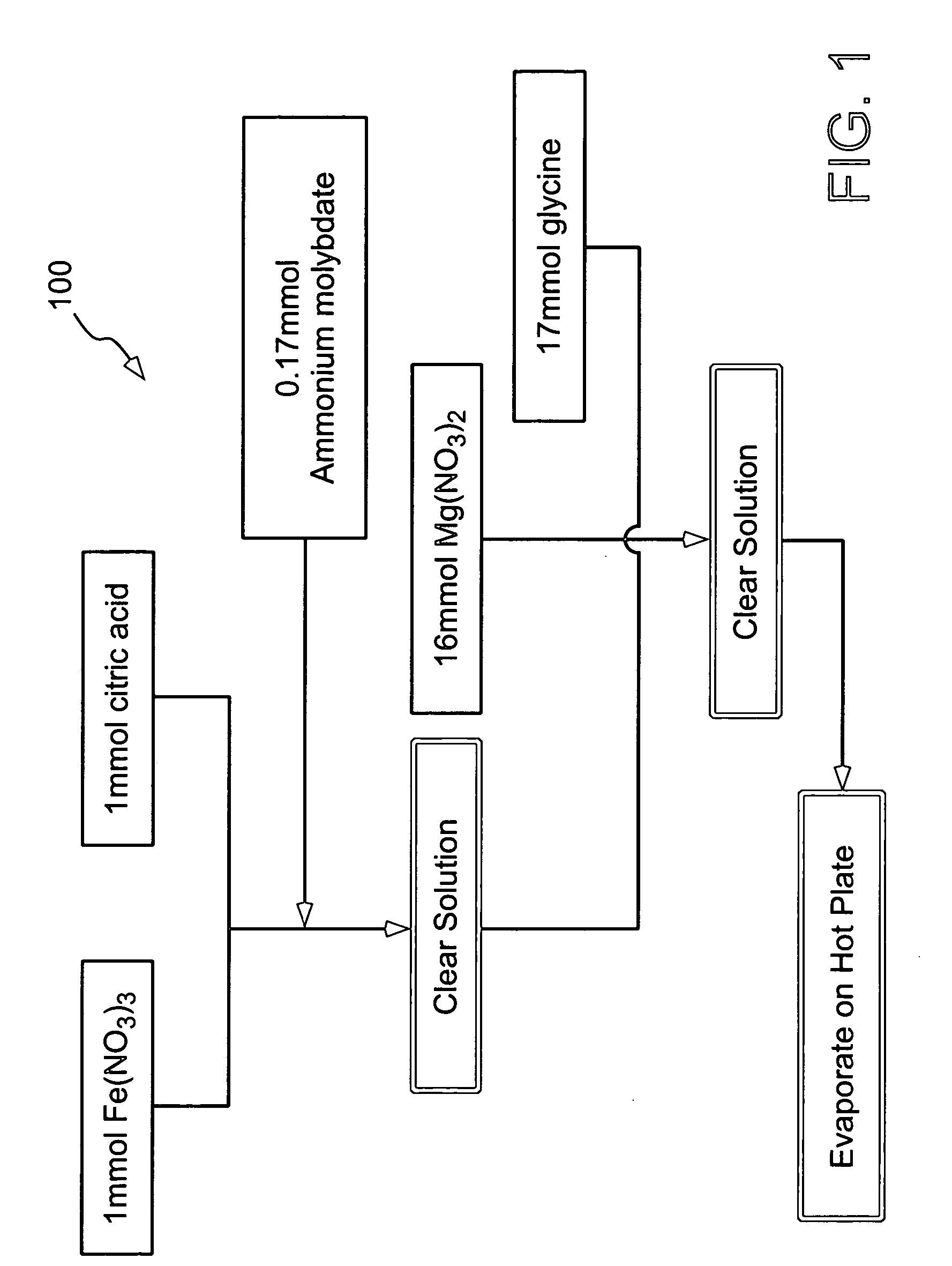
[0031]FIG. 1 illustrates an exemplary scheme for preparation of catalysts. The method 100 is based on a combustion process, such as that generally used to produce complex oxides. This process 100 involves the exothermic reaction of an oxidizer (e.g., metal nitrates) ...


PUM


Abstract

Carbon nanotube material having an outer diameter less than 10 nm and a number of walls less than ten are disclosed. Also disclosed are an electron field emission device including a substrate, an optionally layer of adhesion-promoting layer, and a layer of electron field emission material. The electron field emission material includes a carbon nanotube having a number of concentric graphene shells per tube of from two to ten, an outer diameter from 2 to 8 nm, and a nanotube length greater than 0.1 microns. One method to fabricate carbon nanotubes includes the steps of (a) producing a catalyst containing Fe and Mo supported on MgO powder, (b) using a mixture of hydrogen and carbon containing gas as precursors, and (c) heating the catalyst to a temperature above 950° C. to produce a carbon nanotube. Another method of fabricating an electron field emission cathode includes the steps of (a) synthesizing electron field emission materials containing carbon nanotubes with a number of concentric graphene shells per tube from two to ten, an outer diameter of from 2 to 8 nm, and a length greater than 0.1 microns, (b) dispersing the electron field emission material in a suitable solvent, (c) depositing the electron field emission materials onto a substrate, and (d) annealing the substrate.

Description

RELATED APPLICATION DATA [0001] This application is based on and claims priority under 35 U.S.C. §119 (e) to U.S. Provisional Application No. 60 / 531,978, filed Dec. 24, 2003, the entire contents of which are incorporated herein by reference.STATEMENT REGARDING FEDERALLY SPONSORED RESEARCH OR DEVELOPMENT [0002] At least some aspects of this invention were made with Government support under the sponsorship of NASA, contract no. NAG-1-01061. The Government may have certain rights in this inventionFIELD OF THE INVENTION [0003] A specific type of carbon nanotubes that have enhanced electron field emission properties and a method of synthesizing the carbon nanotubes is disclosed. The method includes a scalable one-step method for catalyst preparation and a process for the growth of nanotubes using chemical vapor deposition methods. It is related to methods of catalyst preparation, methods of nanotube synthesis and the use of the materials in field emission devices. BACKGROUND OF THE INVEN...

Claims


Application Information

Patent Timeline
Patent Type & Authority Applications(United States)
IPC IPC(8): H01J1/14H01J19/06H01K1/04H01J1/304H01J9/02
CPCB82Y10/00B82Y30/00B82Y40/00C01B31/0233H01J2201/30469C01B2202/36H01J1/304H01J9/025C01B2202/04C01B32/162B82B3/0009
Inventor LIU, JIEDU, CHUNSHENGQIAN, CHENGGAO, BOQIU, QIZHOU, OTTO Z.
Owner NURAY TECH
Why Eureka
Try Eureka