Motor control apparatus

a technology of motor control and control device, which is applied in the direction of multiple dynamo-motor starters, dynamo-electric converter control, instruments, etc., can solve the problems of large loss in the circuit, and large power consumption in the battery, so as to achieve the effect of reducing power consumption

Active Publication Date: 2006-03-16
MITSUBISHI ELECTRIC CORP
View PDF19 Cites 3 Cited by
  • Summary
  • Abstract
  • Description
  • Claims
  • Application Information

AI Technical Summary

Benefits of technology

[0009] The invention was developed to resolve the above-described problems, and it is therefore an object of the invention to provide a motor control apparatus, capable of reliably reducing power

Problems solved by technology

Applying high power supply voltage to such a control device causes a greater voltage drop in a power supply circuit, resulting in greater loss in the circuit.
However, there has been the problem in the aforementioned electric power steering apparatus that a power consumption in the battery becomes larger because the switching regulator 4 has been always operated, notwithstanding the cont

Method used


Image

  • Motor control apparatus
  • Motor control apparatus
  • Motor control apparatus

Examples


embodiment 1

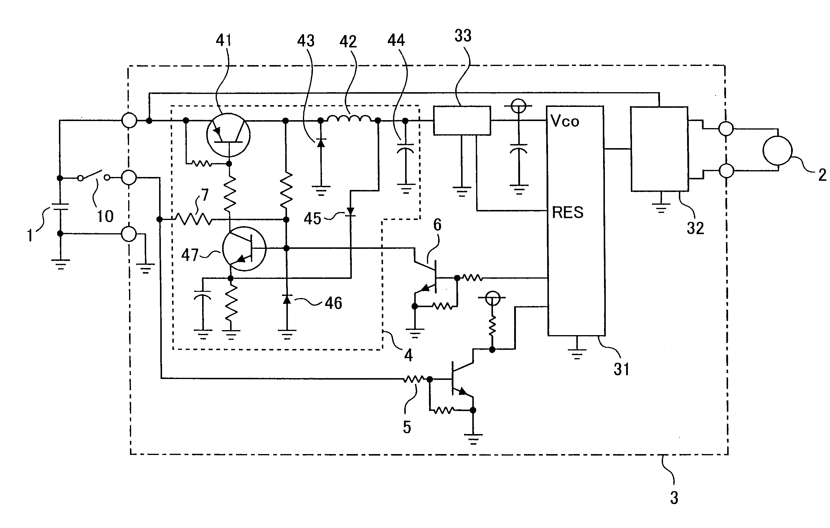
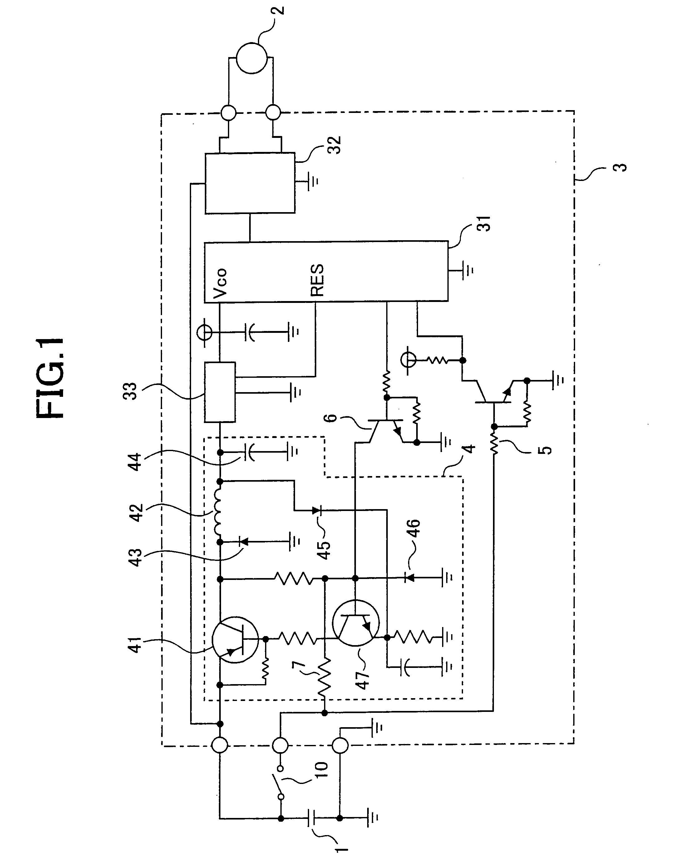
[0016] An embodiment of the present invention will now be described. FIG. 1 shows a first embodiment of the invention, wherein reference numeral 1 denotes a power supply such as a battery; 2, a motor for increasing driver's steering power; 3, a control unit for controlling the motor 2. The control unit 3 is, same as the prior art shown in FIG. 3, equipped with a control means 31 comprising a microcontroller and others, a driving means 32 for driving the motor 2 according to the instruction from the control means 31, and a series regulator 33. The battery 1 supplies a voltage power directly to a driving means 32 for a motor 2 and also supplies a lower voltage stepped down by a switching regulator 4 comprising a DC-DC converter to a control means 31 comprising a microcontroller and others. The switching regulator 4 shown in this embodiment is constituted by a self excited step down-chopper circuit. The series regulator 33 is operated so as to convert a voltage from the switching regul...

embodiment 2

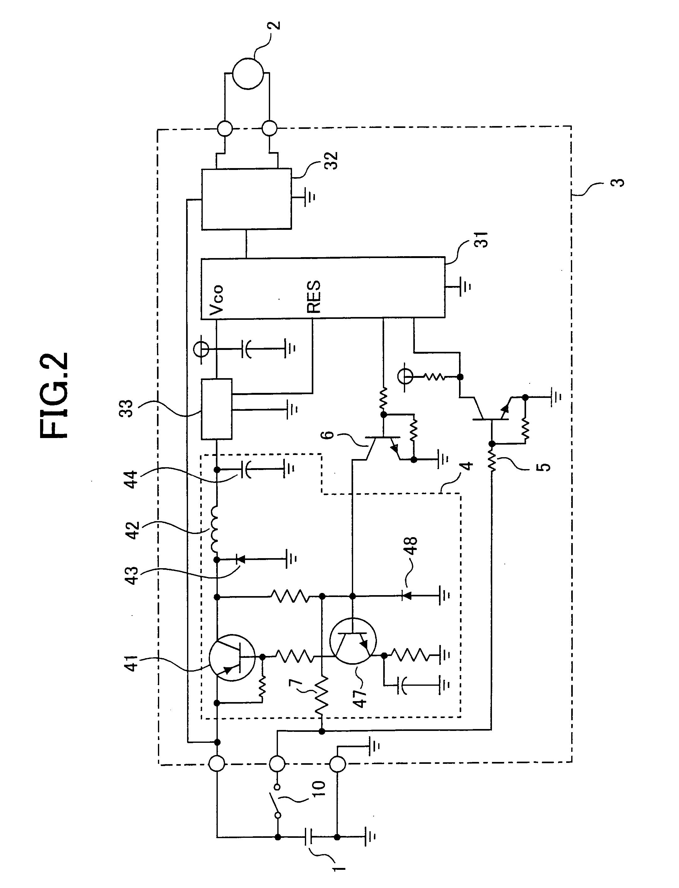
[0024] The second embodiment of the present invention will next be described. FIG. 2 shows an example of the switching regulator 4 constructed of separately excited chopper circuit. Like reference characters designate like component parts in the first embodiment of the invention. This embodiment is different from the first embodiment in the point that there is no second diode 45 through which the output voltage of the switching regulator 4 filtered with the coil 42 and the capacitor 44 is input to the second transistor 47 as a feedback signal. Other point different from the first embodiment is that there exists the resister 48 instead of the zener diode 46 for generating a reference signal. The rest of the components are the same with the first embodiment so that no explanation about those would be necessary.

[0025] The operation of this circuit will next be explained. When the ignition switch 10 is closed, the battery 1 supplies a base current to the second transistor 47 via a resi...


PUM


Abstract

In a motor control apparatus in which a higher voltage is directly applied to a driving unit for a motor from a battery and a lower voltage stepped down by a switching regulator from the battery is also supplied to a control unit, the switching regulator is started its switching by a starting signal supplied from the outside of the motor control apparatus and is stopped its switching by the first stopping signal from the outside of a motor control apparatus and the second stopping signal derived from the control unit.

Description

BACKGROUND OF THE INVENTION [0001] 1. Field of the Invention [0002] The present invention relates to a motor control apparatus, in particular, to a vehicle-steering control apparatus such as an electric power steering apparatus and an automatic steering apparatus for automobiles. [0003] 2. Description of the Prior Art [0004] Heretofore, it has been commonly conducted to increase power supply voltages in order to raise an efficiency of large-power vehicular equipment. Although power supply (battery) voltages in passenger cars, for example, has generally been set at 12V, power supply voltages in commercial cars such as trucks has been set at 24V as they need a greater power supply. It has also been considered to set power supply voltages at 42V even in passenger cars as the number of equipment mounted therein increases. Moreover, in electric cars, a power supply of high voltages as much as 200V or 300V is even mounted. [0005] Whereas, a microcontroller or an operational amplifier impl...

Claims


Application Information

Patent Timeline
IPC IPC(8): H02P5/00B62D5/04H02M3/00H02M3/156H02P29/00
CPCH02M3/156H02M1/36B62D5/0406
Inventor KIFUKU, TAKAYUKI
Owner MITSUBISHI ELECTRIC CORP
Why Eureka
Try Eureka