Motor drive apparatus and motor drive method

a motor drive and motor drive technology, applied in the direction of electronic commutator control, electric motor speed/torque regulation, electric motor, etc., can solve the problems of inability to correctly detect dc components, inability to ignore /i>, and inability to accurately detect dc components, etc., to reduce cost and size, reduce vibration and acoustic noise, and reduce efficiency

Active Publication Date: 2006-03-16
COLLABO INNOVATIONS INC
View PDF5 Cites 49 Cited by
  • Summary
  • Abstract
  • Description
  • Claims
  • Application Information

AI Technical Summary

Benefits of technology

[0023] The motor drive apparatus and motor drive method of the present invention can thus reduce cost and size by sensor-less drive. Vibration and acoustic noise can also be reduced because a non-activation period is not required for roto

Problems solved by technology

The presence of a non-activation period in this prior art method however, causes vibration at the activation changing timing and this vibration results in acoustic noise.
The arrangement of the foregoing prior art leaves the following problems.
Because the third harmonic is typically small, the effect of the offset component of the comparator 104p cannot be ignored as the position detection signal will contain significant position detection error.
Furthermore, if the frequency of the integrated signal Vdip is lower than the cutoff frequency of the lowpass filter when the DC component of the integrated signal Vdip is detected by the lowpass filter, it will not be possible to correctly detect the DC component.
In this case, too, the position detection

Method used


Image

  • Motor drive apparatus and motor drive method
  • Motor drive apparatus and motor drive method
  • Motor drive apparatus and motor drive method

Examples


embodiment 1

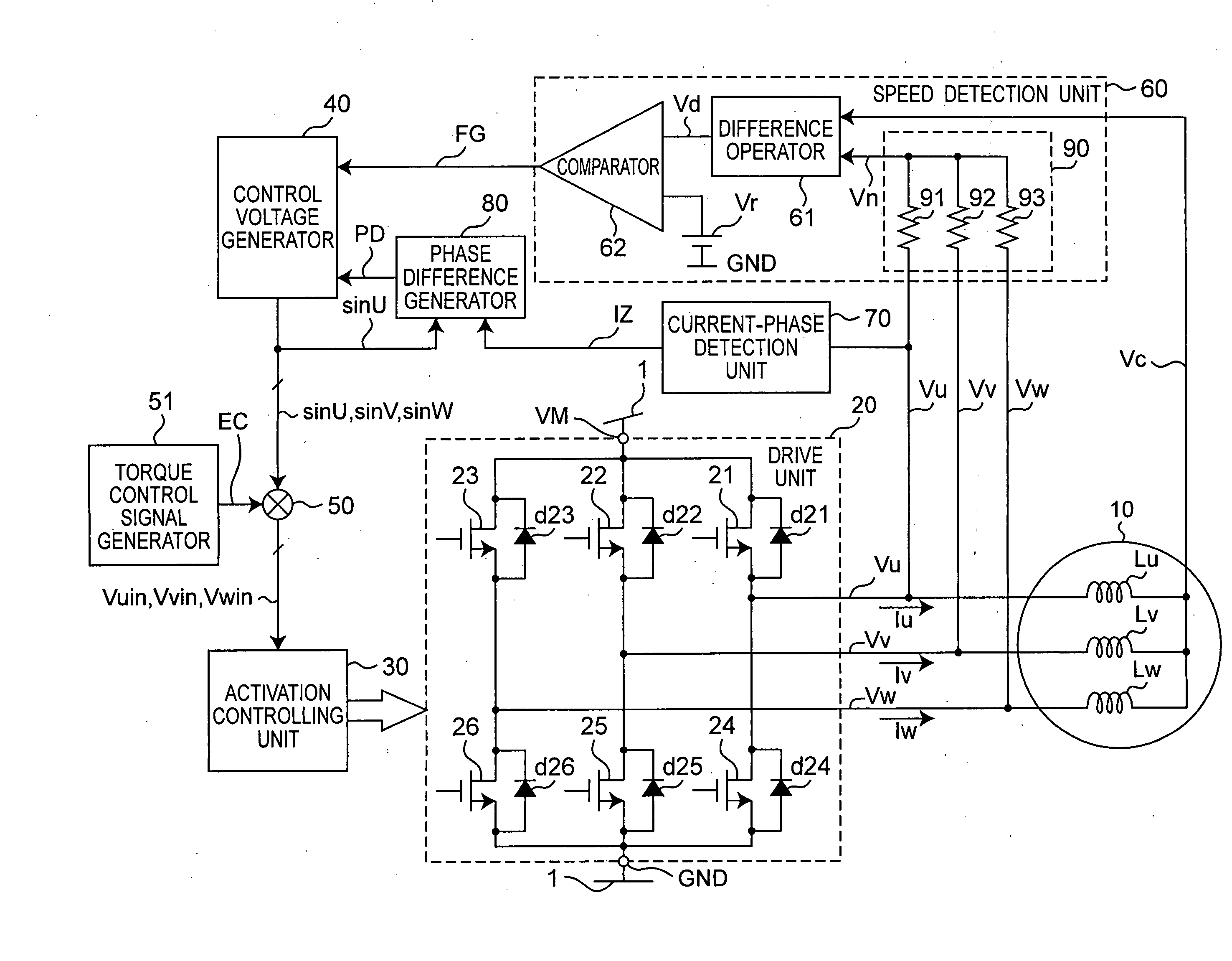
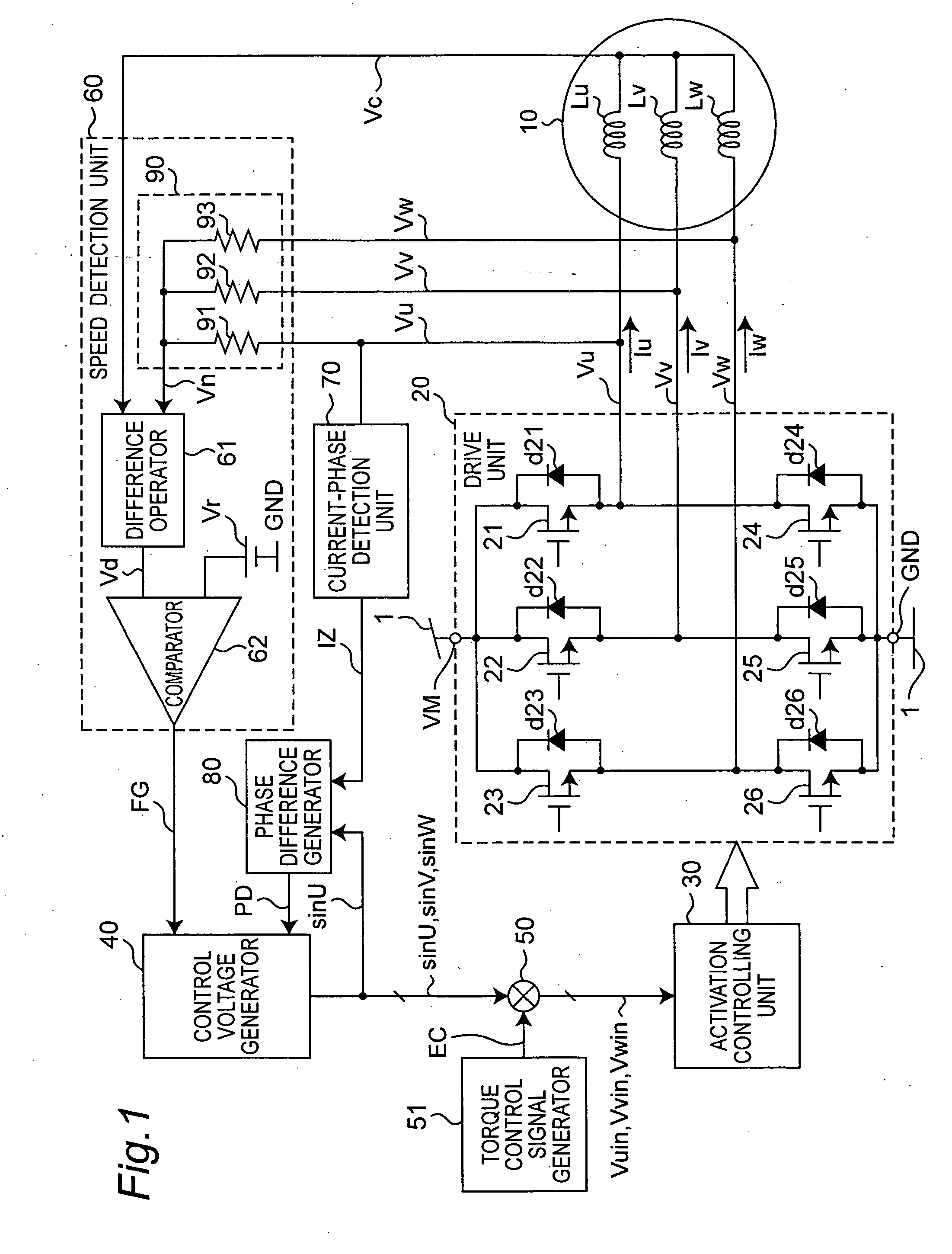
[0074] A motor drive apparatus and motor drive method according to a first embodiment of the present invention are described below with reference to FIG. 1 to FIG. 16. FIG. 1 is a block diagram showing the arrangement of a motor drive apparatus according to this first embodiment. As shown in FIG. 1, a motor drive apparatus according to this first embodiment is composed of a power supply source 1, motor 10, drive unit 20, activation controlling unit 30, control voltage generator 40, multiplier 50, speed detection unit 60, current-phase detection unit 70, and phase difference generator 80.

[0075] The motor 10 which is driven by this motor drive apparatus is composed of a rotor with a field portion in the form of a permanent magnet not shown, and a stator having three-phase windings Lu, Lv, Lw in a Y connection. The drive unit 20 is arranged between terminal VM to which a specific high potential (supply voltage) is supplied from the power supply source 1, and the ground GND to which a ...

embodiment 2

[0173] A motor drive apparatus and motor drive method according to a second embodiment of the invention are described next with reference to FIG. 18 to FIG. 24. FIG. 18 is a block diagram of a motor drive apparatus according to a second embodiment of the invention. This second embodiment differs from the first embodiment in the configuration of the control voltage generator 40A and phase difference generator 80A. Other aspects of the arrangement and operation of this embodiment are the same as described in the first embodiment.

[0174]FIG. 19 is a block diagram showing the specific arrangement of the control voltage generator 40A. The components of this control voltage generator 40A are the same as the control voltage generator 40 in the first embodiment, and differ in that this control voltage generator 40A outputs angle pulse signal AP to phase difference generator 80A.

[0175]FIG. 20 is a block diagram of the phase difference generator 80A. This phase difference generator 80A diffe...

embodiment 3

[0193] A motor drive apparatus and motor drive method according to a third embodiment of the invention are described next with reference to FIG. 25 to FIG. 27. FIG. 25 is a block diagram of a motor drive apparatus according to this embodiment of the invention. This embodiment differs from the second embodiment in the configuration of the phase difference generator 80B. Other aspects of the arrangement and operation of this embodiment are the same as described in the second embodiment.

[0194]FIG. 26 is a block diagram of the phase difference generator 80B. This phase difference generator 80B differs from the phase difference generator 80 of the first embodiment in the inclusion of phase difference calculator 84A and phase difference calculator 84B, phase difference detector 83B, and threshold value setting unit 86. Operation of the phase difference generator 80B is described with reference to the timing chart in FIG. 27. Note that the timing chart in FIG. 27 simply describes the oper...


PUM


Abstract

A motor drive apparatus and motor drive method reduce vibration and acoustic noise by not requiring a non-activation period for rotor position detection, and enable stable, high efficiency motor drive. A control voltage generator generates a control voltage based on the frequency of the speed signal FG output from a speed detection unit, and the amplitude of the control voltage is controlled based on a torque control signal EC. The phase difference generator detects the phase difference between the control voltage and the zero cross signal of the motor current detected from the motor terminal voltages. A control voltage generator controls the phase of the control voltage so that the phase difference goes to zero, thus accomplishing sensor-less motor drive.

Description

BACKGROUND OF THE INVENTION [0001] 1. Field of technology [0002] The present invention relates to a sensor-less motor drive apparatus and motor drive method which do not require a non-activation period for rotor position detection. [0003] 2. Description of Related Art [0004] Brushless motors are now generally used for the spindle motor in hard disk drive and optical disc drive devices, as well as for air conditioner fan motors and compressor drive motors. An inverter and PWM drive control are used to drive brushless motors in order to achieve variable speed control over a wide range of speeds and to reduce power consumption. Hall elements or other position sensors are normally disposed every 120 electrical degrees in a brushless motor with a three-phase winding in order to detect the magnetic pole position of the rotor. This brushless motor is substantially sinusoidal wave driven with the width of 180-degree activation using signals from these position sensors denoting the rotationa...

Claims


Application Information

Patent Timeline
IPC IPC(8): H02P7/00H02P6/08H02P6/06H02P6/18H02P6/182
CPCH02P6/10H02P29/0038H02P25/023H02P6/18H02P25/03H02P29/50
Inventor MORI, HIDEAKIYAMAMOTO, YASUNORI
Owner COLLABO INNOVATIONS INC
Why Eureka
Try Eureka